Eureka AIR delivers breakthrough ideas for toughest innovation challenges, trusted by R&D personnel around the world.

Method of estimating mounting angle error of gyroscopes by using a turning device, and corresponding turning device

a technology of gyroscope and turning device, which is applied in the direction of vehicle position/course/altitude control, process and machine control, instruments, etc., can solve the problems of occupant discomfort, occupant discomfort, and gradual deviation of the reference angle of the inverted pendulum

Active Publication Date: 2014-11-06
TOYOTA JIDOSHA KK
View PDF7 Cites 12 Cited by
  • Summary
  • Abstract
  • Description
  • Claims
  • Application Information

AI Technical Summary

Benefits of technology

The invention allows for the estimation of errors in the mounting of a pitch axis and roll axis angular velocity sensors on an inverted pendulum mobile unit body.

Problems solved by technology

Incidentally, if there is an error in a mounting angle of a pitch axis angular velocity sensor for executing inverted pendulum control over a two-wheeled inverted pendulum vehicle with respect to a reference axis of a body, when the two-wheeled inverted pendulum vehicle turns (turns around its yaw axis), a turning component of the error may be detected by the pitch axis angular velocity sensor and, therefore, an inverted pendulum reference angle may gradually deviate.
This makes an occupant experience discomfort.
This similarly makes the occupant experience discomfort.
In this measure, there is a problem in terms of reduction in the size and weight of the body of the two-wheel inverted pendulum vehicle because a high-accuracy frame for ensuring various accuracies, such as a mounting accuracy between each angular velocity sensor and an inclination sensor that serves as a horizontal reference axis and a mounting accuracy between a sensor block, which includes the angular velocity sensors and the inclination sensor, and the body of the two-wheeled inverted pendulum vehicle, is required, for example.
Such an error of pitch angular velocity through a turn occurs in a relatively low frequency band, so it is conceivable that an error is cancelled by a high-pass filter or using deadband (neutral zone).
However, for example, when a turn direction is changed rightward or leftward minutely, the high-pass filter is not useful at all, so there may be an accumulation of errors in computation process of obtaining a pitch angle by integrating a pitch angular velocity, and the pitch angle may deviate unlimitedly.

Method used


Image

  • Method of estimating mounting angle error of gyroscopes by using a turning device, and corresponding turning device
  • Method of estimating mounting angle error of gyroscopes by using a turning device, and corresponding turning device
  • Method of estimating mounting angle error of gyroscopes by using a turning device, and corresponding turning device

Examples


Embodiment Construction

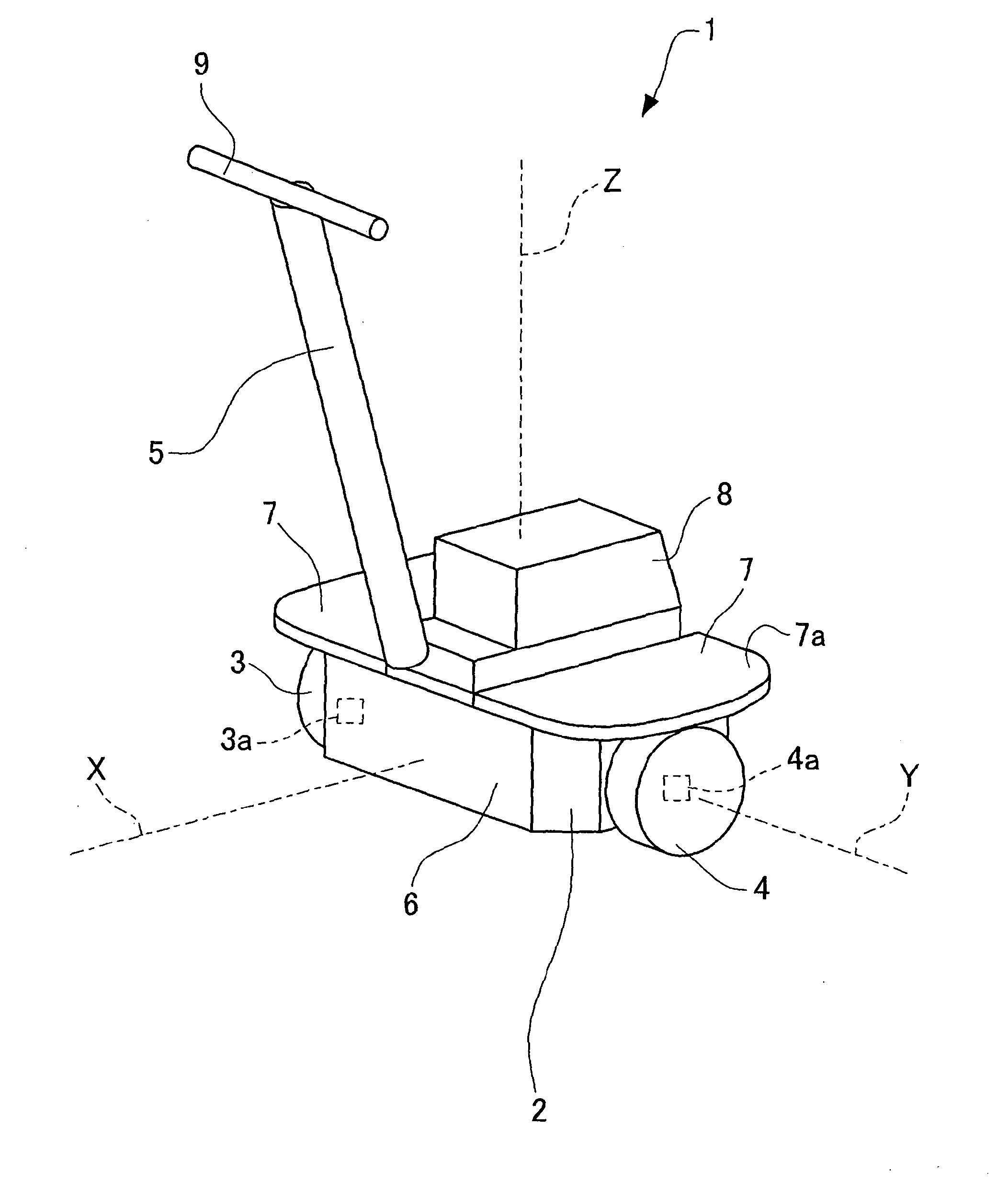
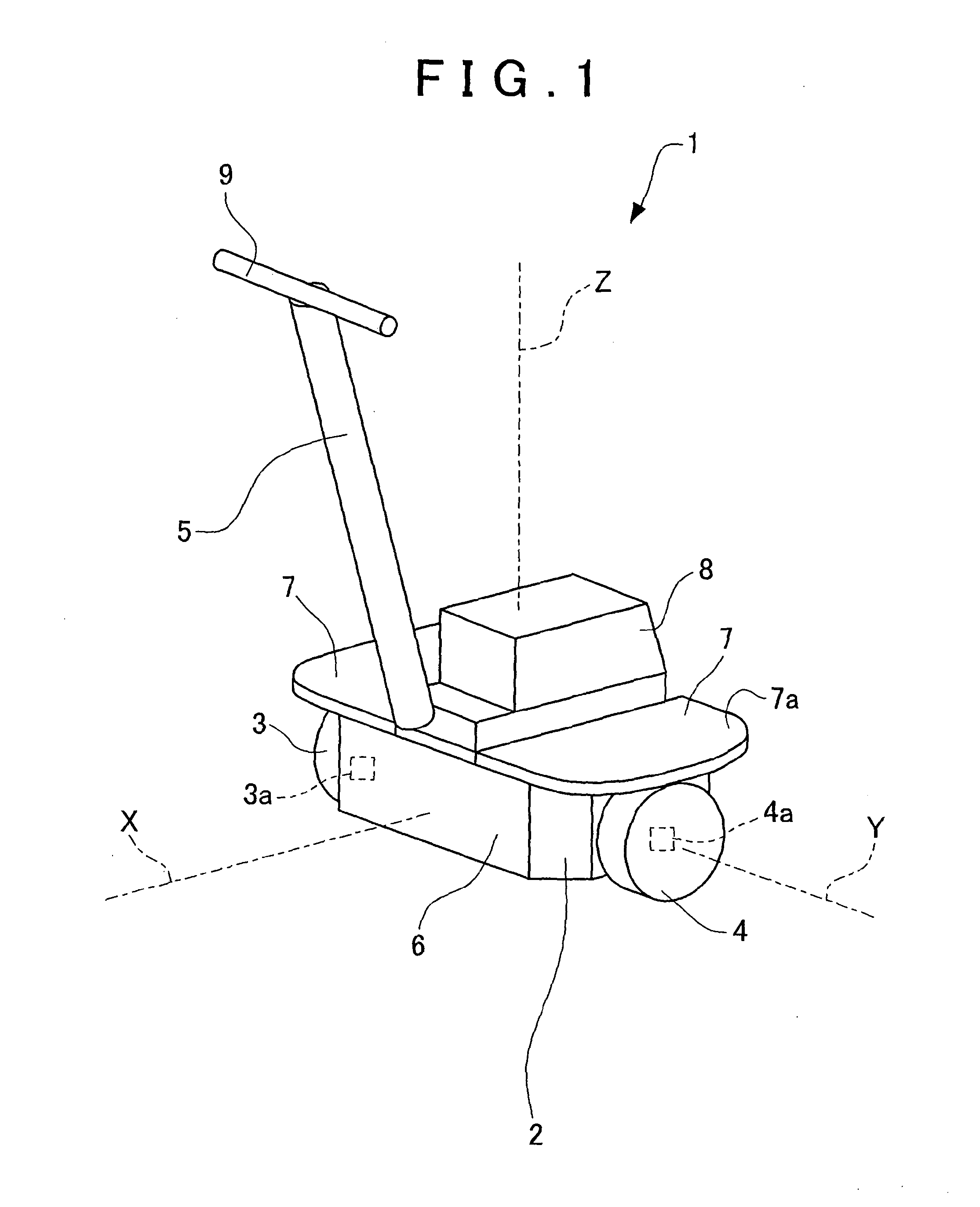
[0021]Hereinafter, a first embodiment of the invention will be described with reference to FIG. 1 to FIG. 5.

[0022]A two-wheeled inverted pendulum vehicle 1 (inverted pendulum mobile unit) shown in FIG. 1 is a vehicle that is used to transport a person (occupant) riding on the two-wheeled inverted pendulum vehicle 1 in a desired direction. The two-wheeled inverted pendulum vehicle 1 moves in response to operation of an occupant who rides on the two-wheeled inverted pendulum vehicle 1.

[0023]The two-wheeled inverted pendulum vehicle 1 is formed of a two-wheeled inverted pendulum vehicle body 2, a right wheel 3, a left wheel 4 and a handle body 5. The right wheel 3 and the left wheel 4 serve as a pair of wheels that are rotatably connected to the two-wheeled inverted pendulum vehicle body 2. The handle body 5 serves as an operation input unit.

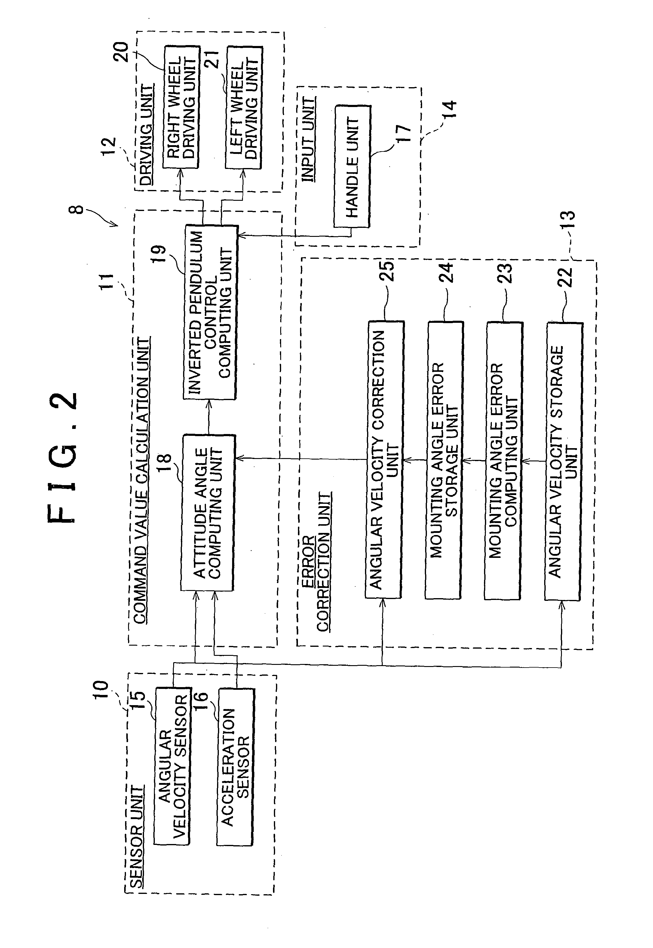
[0024]The two-wheeled inverted pendulum vehicle body 2 is formed of a body lower portion 6, a pair of footrests 7 and a control device 8. A batter...


PUM


Abstract

Bias values of pitch axis and roll axis angular velocity sensors in a stationary state where a reference yaw axis of a two-wheeled inverted pendulum vehicle body is stationary in parallel with a vertical direction are acquired. Bias values of the pitch axis and roll axis angular velocity sensors in a turning state where a two-wheeled inverted pendulum vehicle is turned at a predetermined turning angular velocity in a state where the reference yaw axis of the two-wheeled inverted pendulum vehicle body remains parallel to the vertical direction are acquired. Mounting angle errors of the pitch axis and roll axis angular velocity sensors with respect to the two-wheeled inverted pendulum vehicle body are estimated on the basis of the bias values of the sensors in the stationary state, the bias values of the sensors in the turning state and the predetermined turning angular velocity.

Description

BACKGROUND OF THE INVENTION[0001]1. Field of the Invention[0002]The invention relates to a method of estimating a mounting angle error, and a turning device.[0003]2. Description of Related Art[0004]As a technique of this type, Japanese Patent Application Publication No. 2010-271918 (JP 2010-271918 A) describes attitude control over a two-wheeled inverted pendulum robot that uses an angular velocity sensor (gyro sensor) and an acceleration sensor. Because an output value of the angular velocity sensor degrades over time, a correction value of the angular velocity sensor is obtained by, for example, supporting the two-wheeled inverted pendulum robot with a special jig and then the two-wheeled inverted pendulum robot is rotated at a set rotation speed from a rearmost inclined position to a frontmost inclined position in JP 2010-271918 A.[0005]Incidentally, if there is an error in a mounting angle of a pitch axis angular velocity sensor for executing inverted pendulum control over a two...

Claims


Application Information

Patent Timeline
IPC IPC(8): B62K3/00
CPCB62K3/007B62K11/007G01C21/18G01C25/005G05D1/0891B62J45/4152
Inventor OIKAWA, SUSUMU
Owner TOYOTA JIDOSHA KK
Why Eureka
Eureka Blog
Learn More