Cleaning nozzle for a vacuum cleaner

a vacuum cleaner and nozzle technology, applied in the direction of vacuum cleaners, cleaning equipment, domestic applications, etc., can solve the problems of limited power to obtain the rotation of a rotatable member, such as a brush roll, compared to earlier solutions, and achieve the effect of reducing the total cleaning tim

Active Publication Date: 2014-11-13
AB ELECTROLUX
View PDF4 Cites 36 Cited by
  • Summary
  • Abstract
  • Description
  • Claims
  • Application Information

AI Technical Summary

Benefits of technology

[0017]In embodiments, the at least one radially projecting member is helically arranged along a longitudinal axis of the rotatable member. The helical arrangement ensures proper cleaning of the rotatable member during rotation while at the same time the cleaning interaction is performed within a limited support surface. Thereby, the impact on the rotational speed of the rotatable member is reduced and an effective cleaning action is performed while at the same time normal cleaning operation is maintained.
[0023]In embodiments, at least one protruding part is arranged on the nozzle at a surface turned towards the surface to be cleaned. When a cleaning action is performed, the protruding part prevents the nozzle from tilting due to the force applied on it.
[0025]In embodiments, the radial ribs extend from the rotatable member to the at least one projecting member creating multiple pockets along the rotatable member. The multiple pockets hinder entangled articles from wandering towards the middle segment of the rotatable member. Thereby, entangled articles are distributed along the length of the rotatable member. Even distribution of the entangled articles is advantageous because the layers of entanglement will be fewer. Fewer revolutions of the rotatable member will then be needed for proper cleaning. The total cleaning time is thereby reduced.

Problems solved by technology

Further, by obtaining a limited area of support surface contact with the cleaning member, such as in a single point, the necessary power to obtain rotation of a rotatable member, such as a brush roll, is limited compared to earlier solutions.

Method used


Image

  • Cleaning nozzle for a vacuum cleaner
  • Cleaning nozzle for a vacuum cleaner
  • Cleaning nozzle for a vacuum cleaner

Examples


Embodiment Construction

[0038]The present invention will now be described more fully with reference to the accompanying drawings, in which example embodiments are shown. However, this invention should not be construed as limited to the embodiments set forth herein. Throughout the following description similar reference numerals have been used to denote similar elements, parts, items or features, when applicable.

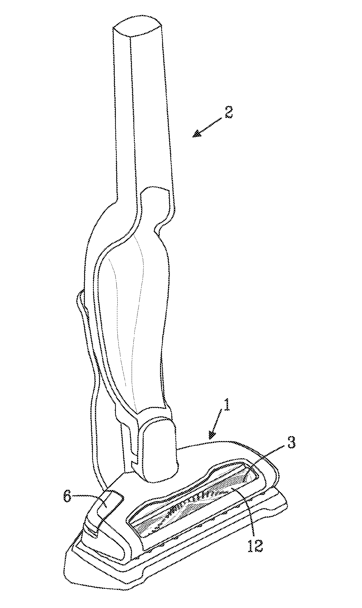
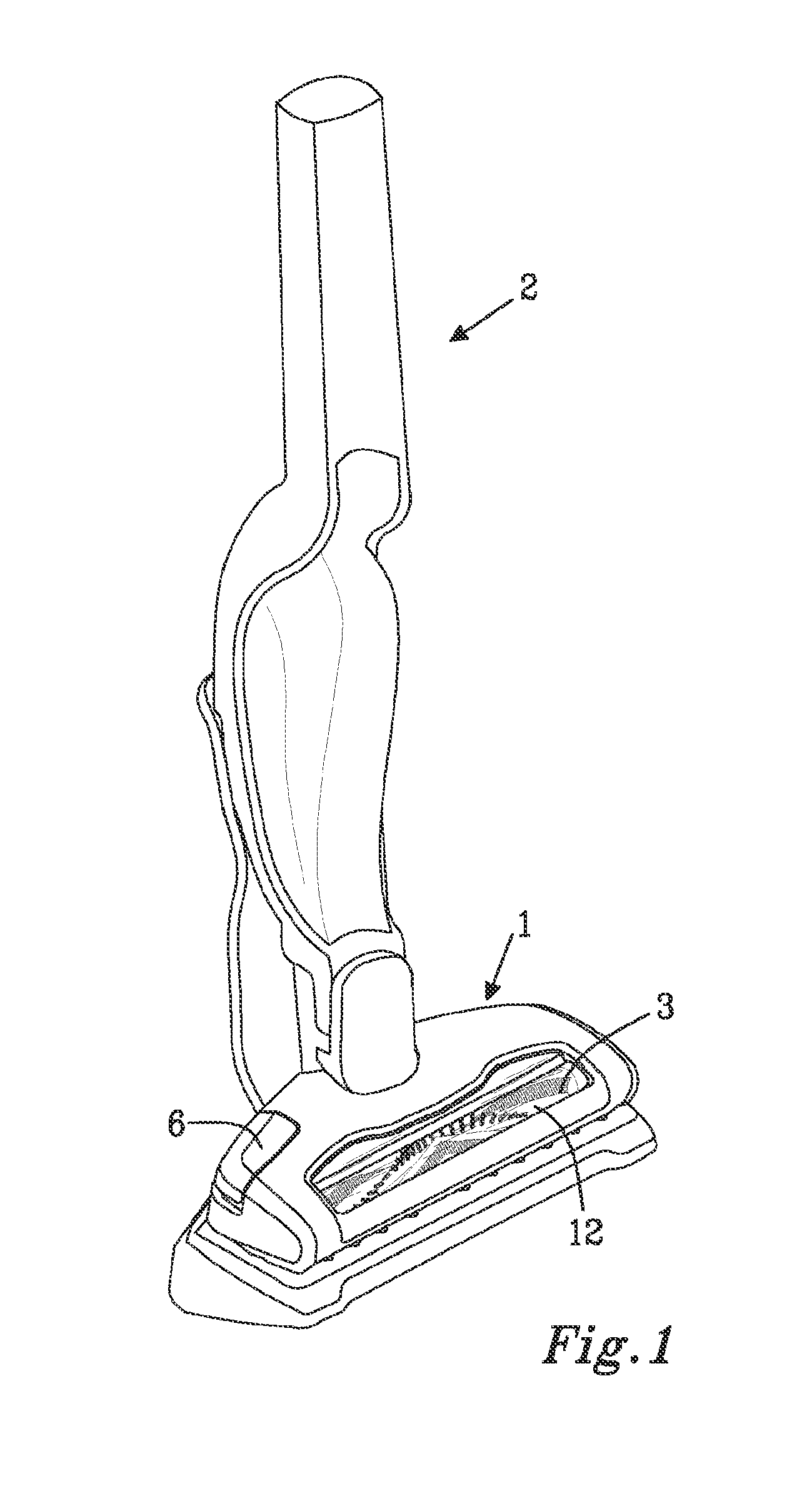
[0039]FIG. 1 illustrates a vacuum cleaner 2 of an upright model comprising a nozzle 1 provided with a rotatable member 3, like a brush roll, for picking up particles from a surface to be cleaned. The nozzle 1 is further provided with a cleaning arrangement for removing articles entangled to the rotatable member 3. The nozzle 1 comprises a cover 12 that at least partly is made of transparent material such that the rotatable member 3 may be visible through the nozzle cover 12. Thereby, the user is able to see if there are a lot of articles like hair entangled to the rotatable member 3. The user initia...


PUM


Abstract

A vacuum cleaner nozzle having a rotatable member arranged around a longitudinal axis for picking up particles from a surface to be cleaned, and a cleaning arrangement for removing articles entangled on the rotatable member. The cleaning arrangement has at least one support surface provided on at least one radially projecting member of the rotatable member, and at least one cleaning member movable between a resting position in which the cleaning member is arranged at a distance from the support surface and at least one cleaning position in the vicinity of the rotatable member. In the cleaning position, the cleaning member co-operates with at least one segment of the support surface to remove any entangled articles from the rotatable member as the rotatable member rotates. The at least one support surface comprises a number of segments arranged at an individual respective radius in relation to the longitudinal axis.

Description

TECHNICAL FIELD[0001]The present invention relates to a nozzle for a vacuum cleaner comprising a rotatable member and a cleaning arrangement for removing articles entangled to the rotatable member. The invention is intended for battery powered vacuum cleaners as well as mains-operated vacuum cleaners. The nozzle according to the present invention is further envisaged for robotic vacuum cleaners.BACKGROUND OF THE INVENTION[0002]In vacuum cleaning nozzles provided with a rotatable member, i.e. a rotatable brush roll, it is known that threads, lint, human or animal hairs or any other fibrous material tend to cling or wrap around adhere to the brush roll during operation of the vacuum cleaner. This may impair the functioning of the cleaning nozzle.[0003]In WO2009 / 117383A2 it is disclosed a cleaning nozzle for a vacuum cleaner provided with a rotary brush having projecting friction surfaces and one or more cleaning members for removing debris that has been wrapped around the rotary brush...

Claims


Application Information

Patent Timeline
Patent Type & Authority Applications(United States)
IPC IPC(8): A47L9/04
CPCA47L9/0477
Inventor ERIKSSON, HENRIK
Owner AB ELECTROLUX
Why Eureka
Try Eureka