Device for reducing pressure and velocity of flowing fluid

a technology of flow fluid and pressure, applied in the direction of valve details, valve arrangement, thin material handling, etc., can solve the problems of increasing noise generation, corrosion, abrasion, noise generation, etc., and achieve the effect of suppressing negative effects, and reducing the pressure and velocity of a flowing fluid

Inactive Publication Date: 2014-11-13
SDD CO LTD
View PDF9 Cites 10 Cited by
  • Summary
  • Abstract
  • Description
  • Claims
  • Application Information

AI Technical Summary

Benefits of technology

[0044]According to the present invention, the device for reducing the pressure and velocity of a flowing fluid is configured wherein under the condition where a high differential pressure occurs between inlet and outlet sides of a fluid processing device like a valve, the pressure of the flowing fluid passing through the fluid processing device can be effectively reduced and the flowing velocity of the fluid can be restricted to an appropriate level, thus suppressing negative effects such as noise, vibration, cavitation, corrosion, and so on.
[0045]That is, the curved flow passages and the vortex forming spaces are repeatedly formed in the shape of the grooves or holes penetratedly formed on the discs of the cage, and accordingly, the flow of the fluid at a rapid velocity forms turbulent flows from which irregular vortexes are produced in the flow passages, so that the pressure of the fluid and the flow velocity of the fluid are decreased through the loss of energy caused by the flow resistance of the fluid, that is, velocity head loss, thus preventing the above-mentioned negative effects occurring from high flow velocity.
[0046]According to the conventional three-dimensional flow passage structure (U.S. Pat. No. 5,819,803), only the cross-sectional area of the flow passage is drastically expanded and drastically contracted to form a perpendicularly curved flow passage. In this case, a pair of discs having different shapes from each other is provided wherein one disc forms a radial flow of fluid and the other induces the radial flow of fluid, thus forming the curved flow passage. According to the present invention, contrarily, the device for reducing the pressure and velocity of a flowing fluid removes the problems such as noise, vibration, corrosion and abrasion caused by the local velocity increment and the drastic variations of the pressure of the fluid. According to the thermodynamic and fluid dynamic features of the fluid, that is, the device of the present invention forms the vortex forming spaces just before the flow passages are changed to the vertical direction so as to greatly increase the resistance coefficients every the direction changing portion to the vertical direction in the flow passages.
[0047]According to the present invention, if the vortex forming spaces exist just before the directions of the flow passages are changed, the resistance coefficient of of the curved portion is more increased by about 1.2 times than that having no vortex forming spaces, as indicated by the following equation 4.
[0048]In this case, the fluid forms the vortexes in the vortex forming spaces to cause the loss of rotational energy therefrom, and accordingly, the kinetic energy of the fluid passed through the vortex forming spaces is lost by the rotational energy used for the vortex formation. If drastic pressure variations occur due to external factors (for example, in the state of the drastic acceleration of the fluid), the vortex forming spaces serve as the impact-absorbing spaces where the impact of fluid can be absorbed before the fluid is curved perpendicularly, thus effectively reducing the kinetic energy of the fluid.
[0049]According to the present invention, further, the conventional problem wherein the formation of the plurality of zigzag flow passages makes the size of the device bulky is solved to allow the fluid processing device to be made to a compact size.

Problems solved by technology

If the flow rate of the fluid becomes fast in fluid processing equipment, corrosion, abrasion, and noise are increased.
For example, if the flow rate of water flowing in the equipment made of carbon steel is more than 30-40 ft / sec, corrosion occurs.
If the flow velocity of the fluid becomes fast at a specific portion (for example, a local portion of an orifice or valve), the generation of noise is accelerated.
Further, if the pressure is recovered to the vapor pressure or more at the rear end of the fluid processing device, cavitation occurs.
Further, if the hole through which the fluid is passed is divided into a plurality of parts, peak frequency of noise is moved to high parts.
According to the flow control device disclosed in U.S. Pat. No. 6,615,874, however, a relatively low flow resistance occurs from one zigzag flow passage, and therefore, the zigzag flow passages should be plurally formed so as to obtain a desired flow resistance value, which makes the size of the device undesirably increased.
So as to obtain a desired flow resistance, therefore, the number of zigzag flow passages should be increased, which undesirably causes the size of the device and the space occupied by the device to be bulky.
If the number of T-shaped flow passage holes is decreased, the number of direction changing times of the curved flow passages is reduced and accordingly it is difficult to reduce the flow velocity and pressure of the fluid to a desired level.
If the radial size of the disc is increased, on the other hand, the radial size of the device is increased, and accordingly, the overall size of the device becomes large.

Method used


Image

  • Device for reducing pressure and velocity of flowing fluid
  • Device for reducing pressure and velocity of flowing fluid
  • Device for reducing pressure and velocity of flowing fluid

Examples


Embodiment Construction

[0061]Hereinafter, an explanation on a device for reducing the pressure and velocity of a flowing fluid according to the present invention will be in detail given with reference to the attached drawings. In the description, a valve is provided as a fluid processing device, but in addition to the valve, the present invention may be applied to all kinds of devices having a high differential pressure between inlet and outlet sides.

[0062]Basic Configuration

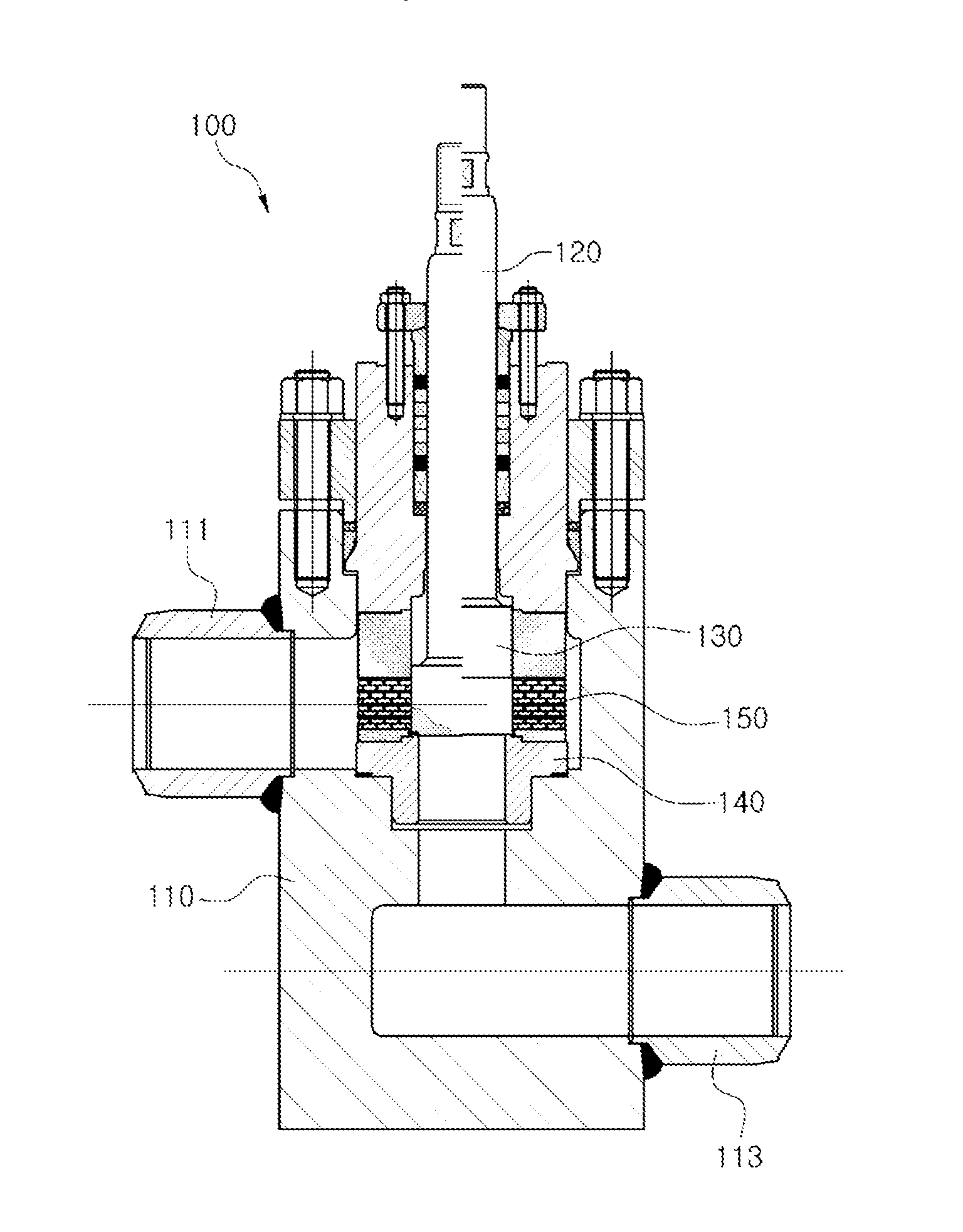
[0063]FIG. 6 is a longitudinal sectional view showing a valve on which a device for reducing the pressure and velocity of a flowing fluid according to the present invention is mounted, FIG. 7 is a perspective view showing the basic configuration of the device for reducing the pressure and velocity of a flowing fluid according to the present invention, FIGS. 8 to 10 show the basic configuration of the device for reducing the pressure and velocity of a flowing fluid according to the present invention, and FIGS. 11 and 12 show the arrang...


PUM


Abstract

The present invention relates to a device for reducing the pressure and velocity of a flowing fluid. According to the present invention, a cage has discs having through holes which come into close contact with an outer surface of a plug. The discs are stacked in a direction of a central shaft of the cage. Flow passage portions are formed on the stacked discs, wherein the flow passage portions communicate with the outer surfaces of the discs, and the inner surfaces which correspond to the through-holes so as to form flow passages between the stacked discs, and the direction of the flow passages changes to a circumferential direction and a vertical direction on the stacked discs. Additionally, the discs are stacked by applying one or more flow passage portions based on the number of times of the direction of the flow passage changes and the number of flow passage portions to the discs so as to control the increasing velocity of the flow rate of the fluid according to the degree of opening formed upon upward movements of the plug.

Description

TECHNICAL FIELD [0001]The present invention relates to a device for reducing the pressure and velocity of a flowing fluid, and more particularly, to a device for reducing the pressure and velocity of a flowing fluid wherein under the condition where a high differential pressure occurs between inlet and outlet sides of a fluid processing device like a valve, the pressure of the flowing fluid passing through the fluid processing device can be effectively reduced and the flow velocity of the fluid can be restricted to a given level, thus suppressing negative effects occurring from the flowing fluid, such as noise, vibration, cavitation, corrosion, and so on.BACKGROUND ART [0002]In the field wherein the precision of the control for the pressure or velocity of a fluid is required under the extreme condition of a high differential pressure, generally, the velocity and pressure of the flowing fluid should be appropriately controlled, and also, a fluid resistor having orifice, labyrinth or ...

Claims


Application Information

Patent Timeline
Patent Type & Authority Applications(United States)
IPC IPC(8): F16K47/08
CPCF16K47/08Y10T137/86759F16K47/04F16K47/14
Inventor KWON, KAB JUKIM, YOUNG BUMSEO, DONG PYOKIM, JIN HONG
Owner SDD CO LTD
Why Eureka
Try Eureka