Tire testing machine conveyor

Active Publication Date: 2014-11-13
KOBE STEEL LTD
View PDF7 Cites 6 Cited by
  • Summary
  • Abstract
  • Description
  • Claims
  • Application Information

AI Technical Summary

Benefits of technology

[0011]With such a configuration, the driving unit (the pulley and the motor) is driven so as to rotate the driving shaft, the pair of second left and right pulleys connected to each other by the driving shaft is rotated so as to rotate the pair of first left and right pulleys that stretch the pulley belts between the pair of second left and right pulleys and the pair of first left and right pulleys, the pair of first left and right pulleys is rotated so as to rotate any one of the pair of front and rear belt driving pulleys connected to the pair of first left and right pulleys, and the conveyor belts stretched between the belt driving pulleys move, thereby stably driving the center conveyor. Then, since the driving unit is provided at the outer lower side of the center conveyor in the width direction, a space is formed between the pair of left and right belt driving pulleys of the center conveyor, and hence the downstream front end of the entrance conveyor or the upstream front end of the exit conveyor may be located in the space between the pair of left and right belt driving pulleys. For this reason, the center conveyor and the entrance conveyor or the exit conveyor may be appropriately disposed without any gap or step therebetween and any interference between the driving units. Further, when the downstream end of the entrance conveyor or the upstream end of the exit conveyor is disposed between the pair of conveyor belts of the center conveyor, the plurality of conveyors is disposed so as to overlap each other. In addition, when the entrance conveyor or the exit conveyor is driven so as to be synchron

Problems solved by technology

For this reason, when there is an unnecessary gap or step between the plurality of conveyors, a slippage occurs between the tire and the conveyor at the portion, and hence there is a concern that the tire may not be

Method used


Image

  • Tire testing machine conveyor
  • Tire testing machine conveyor
  • Tire testing machine conveyor

Examples


Example

[0027]Hereinafter, a specific example of an embodiment of a tire testing machine conveyor according to the present invention will be described by referring to the drawings.

[0028]Furthermore, the description below is merely an example, and does not show the application limit of the tire testing machine conveyor according to the present invention. That is, the tire testing machine conveyor according to the present invention is not limited to the embodiment below, and may be modified into various forms within the limit of claims.

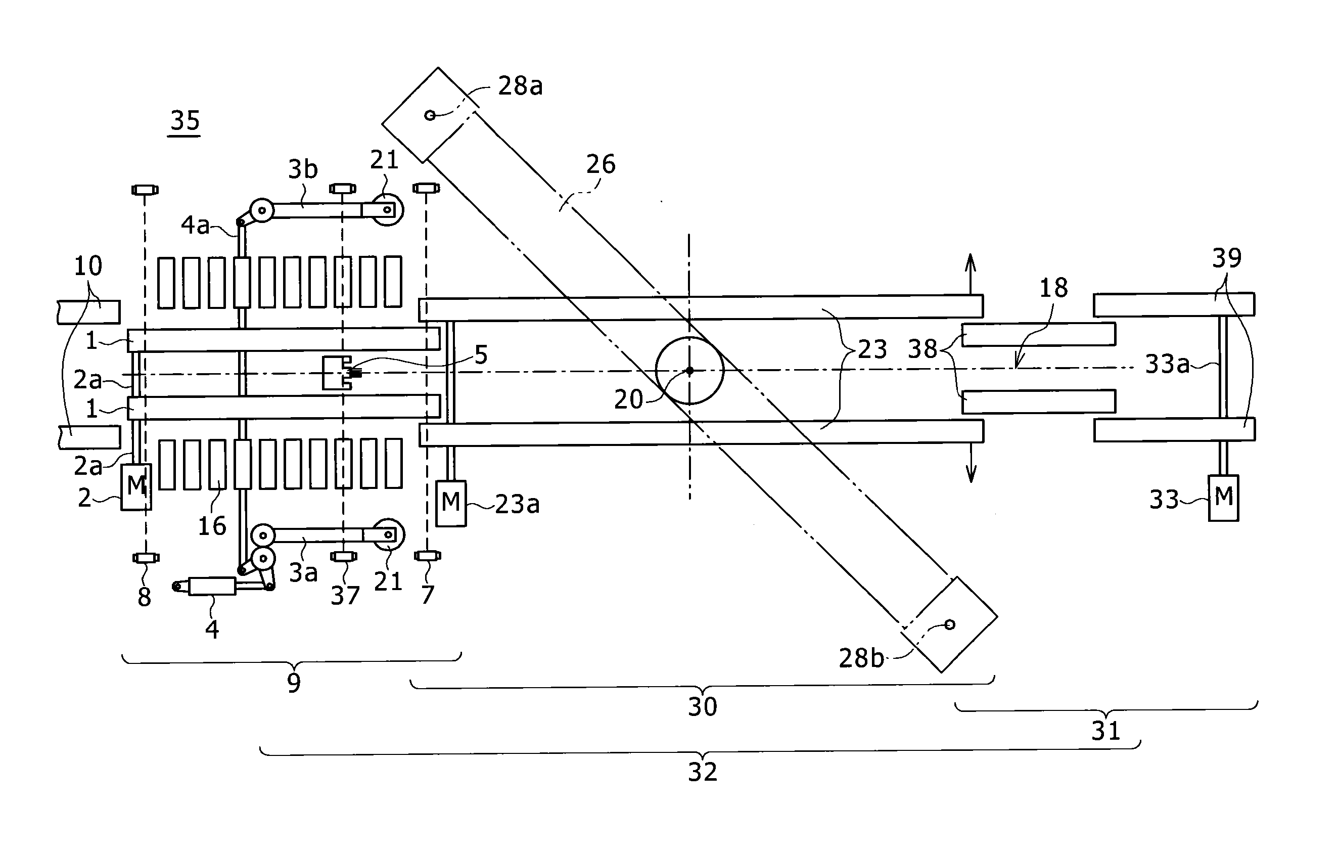
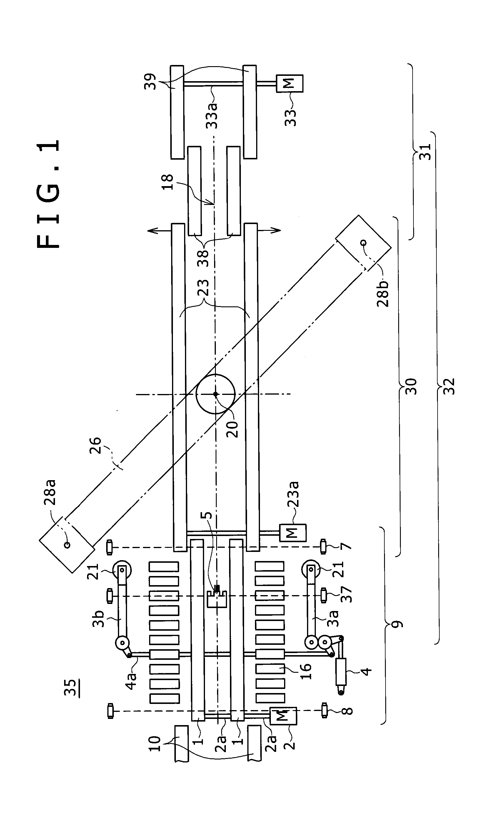
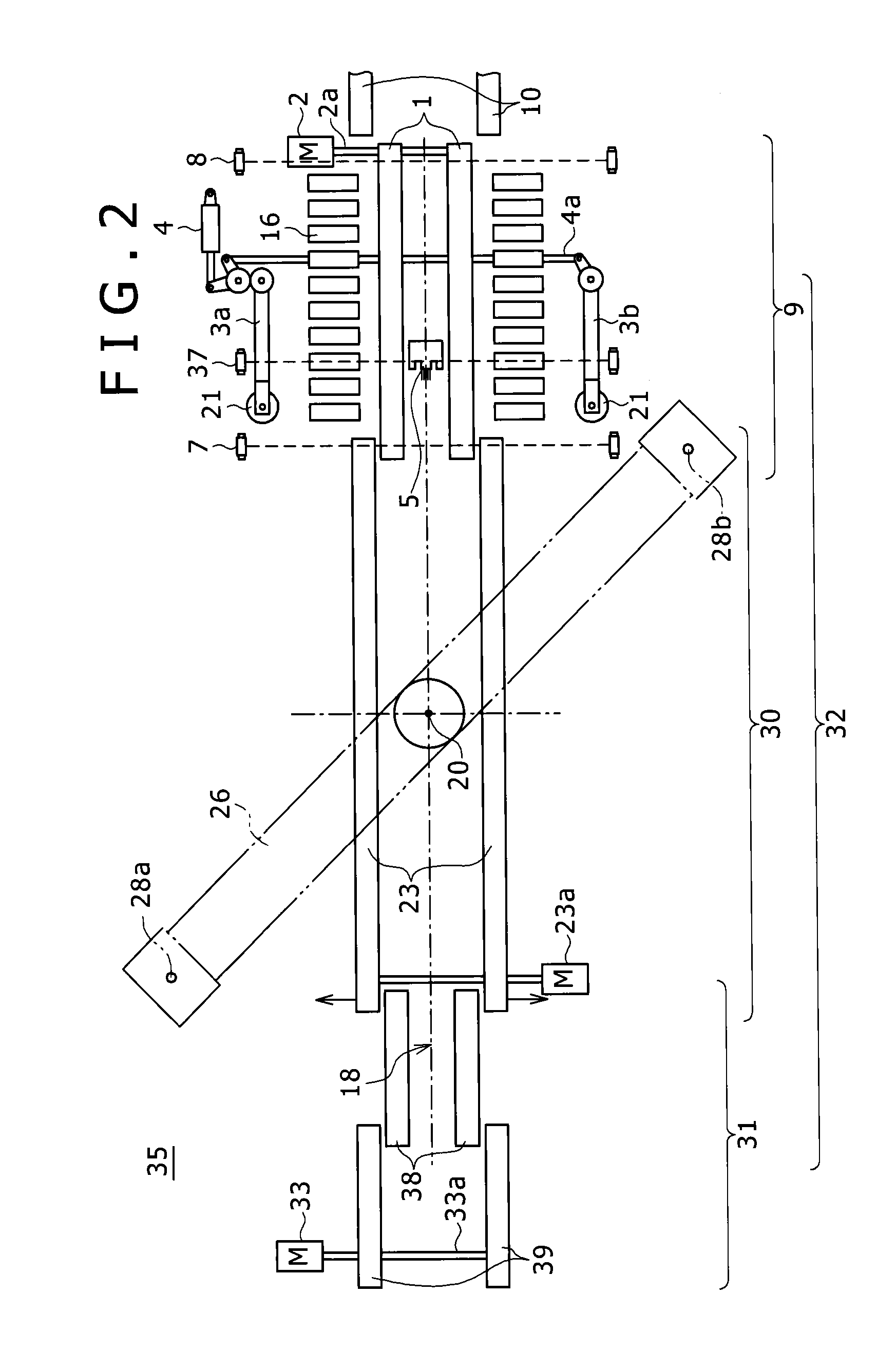
[0029]As illustrated in FIGS. 1 and 3, a tire testing machine conveyor 32 that is used in a tire testing machine 35 according to this embodiment includes an entrance conveyor 9 that conveys a tire 11 conveyed and input from a customer conveyor 10 while the tire 11 is placed on the entrance conveyor 9 in a falling state, a center conveyor 30 that is connected to the downstream side of the entrance conveyor 9 and extends into a test station (a test table) 34, and...


PUM


Abstract

A plurality of conveyors including a center conveyor are appropriately disposed without any gap or step and any interference between driving units. The center conveyor includes a pair of left and right belt driving pulleys that are provided at the front and rear sides in the conveying direction so as to stretch loop-shaped conveyor belts therebetween and are provided at both sides in the width direction, a pair of first left and right pulleys that is connected to each other through a connection shaft disposed on rotation axes of the belt driving pulleys at both outer sides in the width direction, a pair of left and right second pulleys that is provided below the first pulleys at both outer sides in the width direction so as to stretch loop-shaped pulley belts between the first and second pulleys and includes a common rotation axis, a driving shaft that is disposed on rotation axes of the second pulleys and is connected to the pair of second left and right pulleys, and a motor that is connected to an end of the driving shaft.

Description

BACKGROUND OF THE INVENTION[0001]1. Field of the Invention[0002]The present invention relates to a tire testing machine conveyor that sends a tire to a tire testing machine.[0003]2. Description of the Related Art[0004]When there is any non-uniform portion having a variation in elastic modulus or dimensional shape in the circumferential direction of a tire attached to an automobile or the like, the non-uniform portion causes a vibration during a high-speed rotation, and hence running performance is degraded. For this reason, the tire is subjected to a circumferential uniformity test by a tire testing machine after a vulcanizing process. The tire testing machine performs a test in a manner such that a bead portion of the inner periphery of the tire is interposed between rim members, the tire is attached to a rotating spindle, a predetermined internal pressure is applied to the tire, and the tire is rotationally driven while being pressed against a road surface replacement member such ...

Claims


Application Information

Patent Timeline
IPC IPC(8): B65G37/00
CPCB65G37/00G01M17/021G01M17/022
Inventor WAKAZONO, TAKEHIKOSOEJIMA, MUNENORI
Owner KOBE STEEL LTD
Why Eureka
Try Eureka