Conveyance apparatus, and weighing and packaging system provided therewith

Inactive Publication Date: 2007-11-08
ISHIDA CO LTD
View PDF10 Cites 11 Cited by
  • Summary
  • Abstract
  • Description
  • Claims
  • Application Information

AI Technical Summary

Benefits of technology

[0017] According to the conveyance apparatus of the first aspect of the present invention, each delivery table is moved to the standing position by the drive unit when each delivery table receives a flat article from the upstream side. Then, the drive unit causes each delivery table to deliver the received article to the holding unit and to simultaneously orderly place the articles from front to rear on the holding unit, so that the articles are held by the holding unit and are accumulated thereon in a front-to-rear direction in the standing position. In addition, the drive unit causes each delivery table to operate in synchronization with the operation of the holding unit, so that the accumulation process will be stable. Therefore, unlike conventional apparatuses, the present conveyance apparatus does not need to be additionally provided with a relatively long and large position changing device configured to move the articles to the standing position, therefore preventing the apparatus from increasing in size as a whole.
[0089] According to the conveyance apparatus of the thirty-third aspect of the present invention, it is possible, with a simple structure, to switch between suctioning and discharging the articles on the receiving surface of each delivery table, by causing each delivery table to move while causing the same to contact with the opening of the chamber portion connected to each of the suction unit and the blowout portion.

Problems solved by technology

Consequently, the entire apparatus becomes larger, which will be a problem when cost and / or installation space is limited.
However, for example, when the thicknesses of packaged articles X having the same contents vary in each packaged article X, or when the frictional properties and flexibility of the packaging materials of the packaged articles X are different in each packaged article X, it may not be possible to stably maintain the standing position of the articles X.
Therefore, unlike the conveyance apparatus described in Japanese Patent Application Publication No. 2003-212338, problems such as an increased size of the conveyance apparatus or the instability of the position of the articles X do not exist.
However, as shown in FIG. 17, when the position of each article X is changed, the delivery table 231 largely rotates about a mounting base on the running surface as a rotation support point, so that the centrifugal force F′ acting on the articles X will be large, which may cause a problem in which the articles X jump off of the delivery table 231.

Method used


Image

  • Conveyance apparatus, and weighing and packaging system provided therewith
  • Conveyance apparatus, and weighing and packaging system provided therewith
  • Conveyance apparatus, and weighing and packaging system provided therewith

Examples


first embodiment

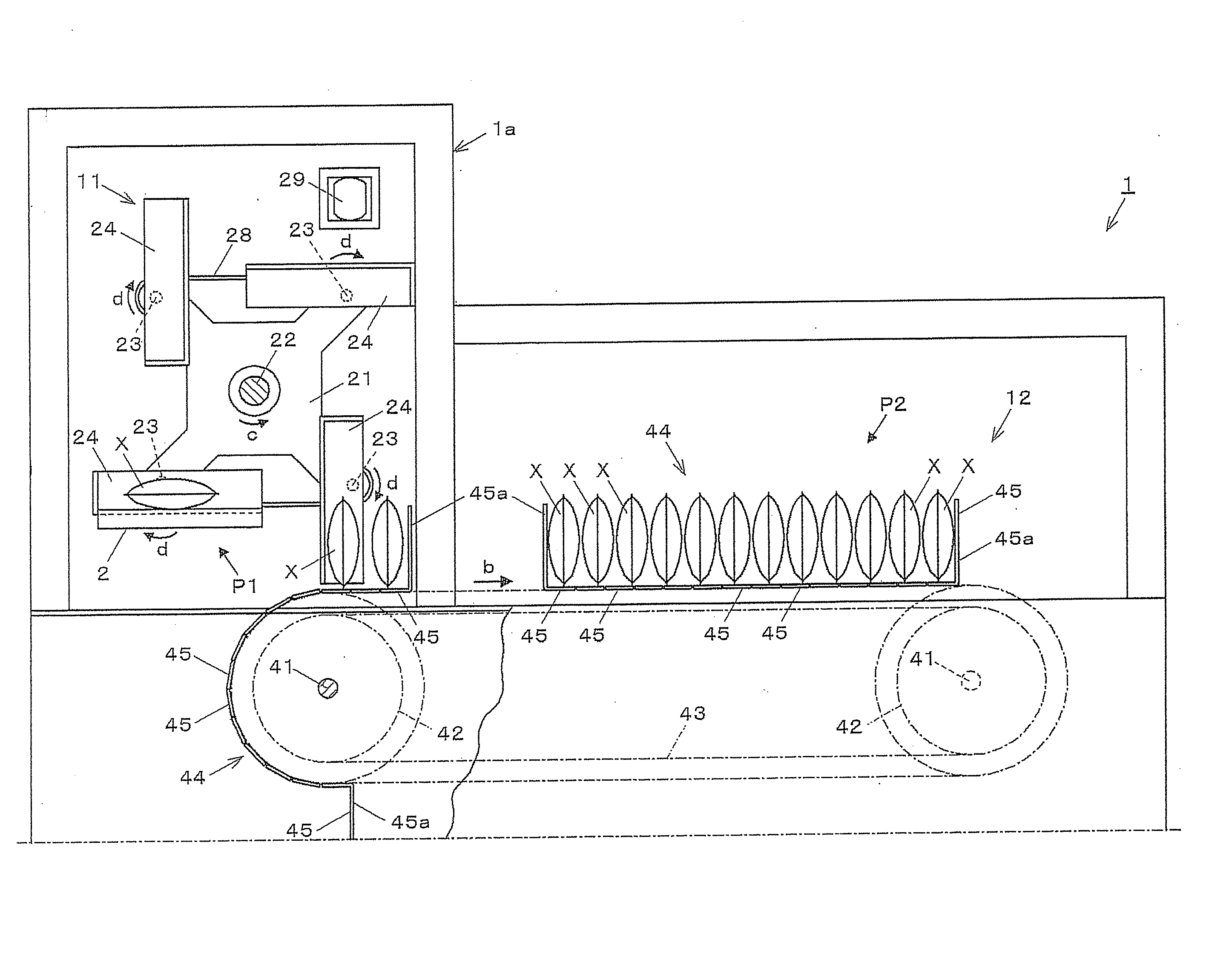
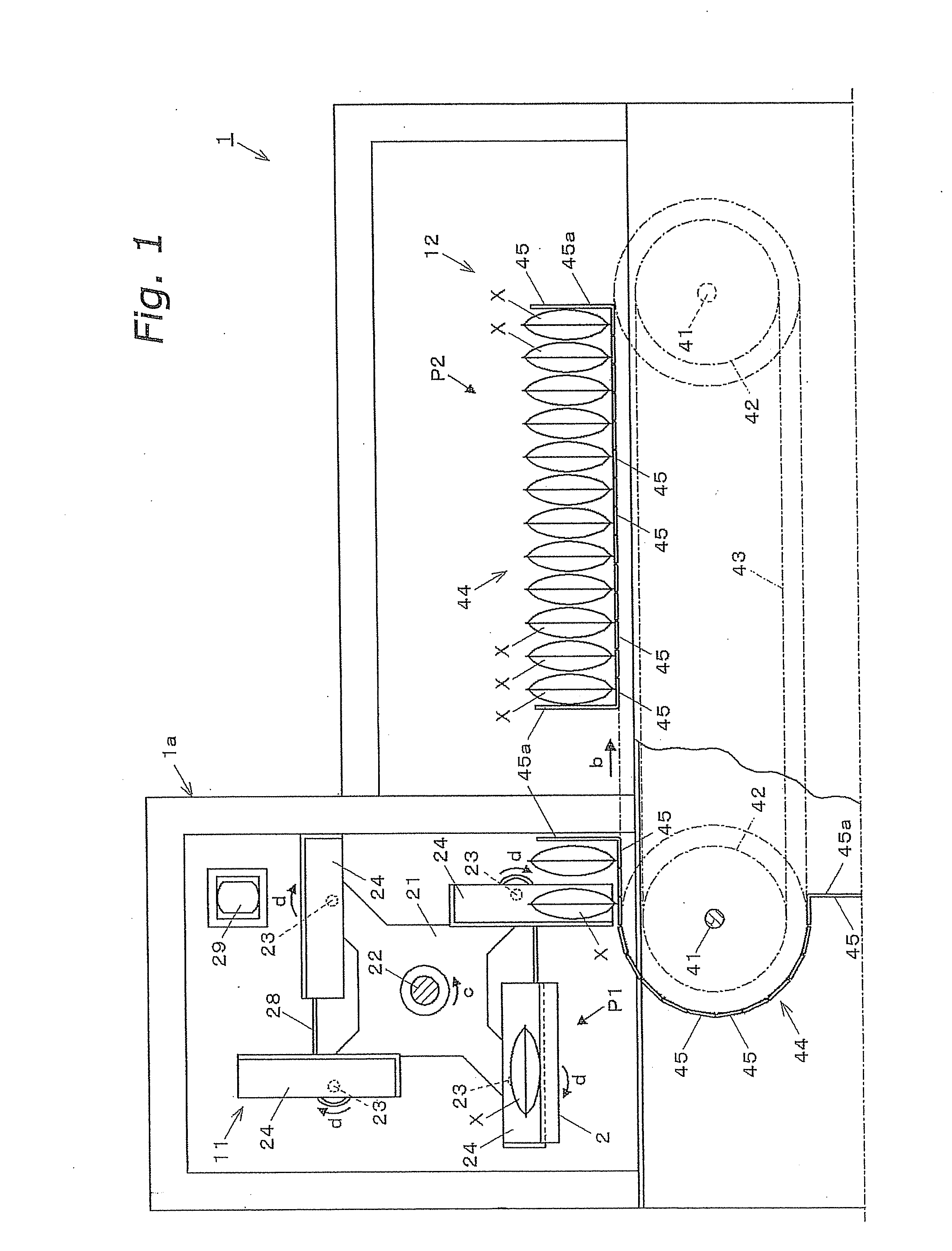
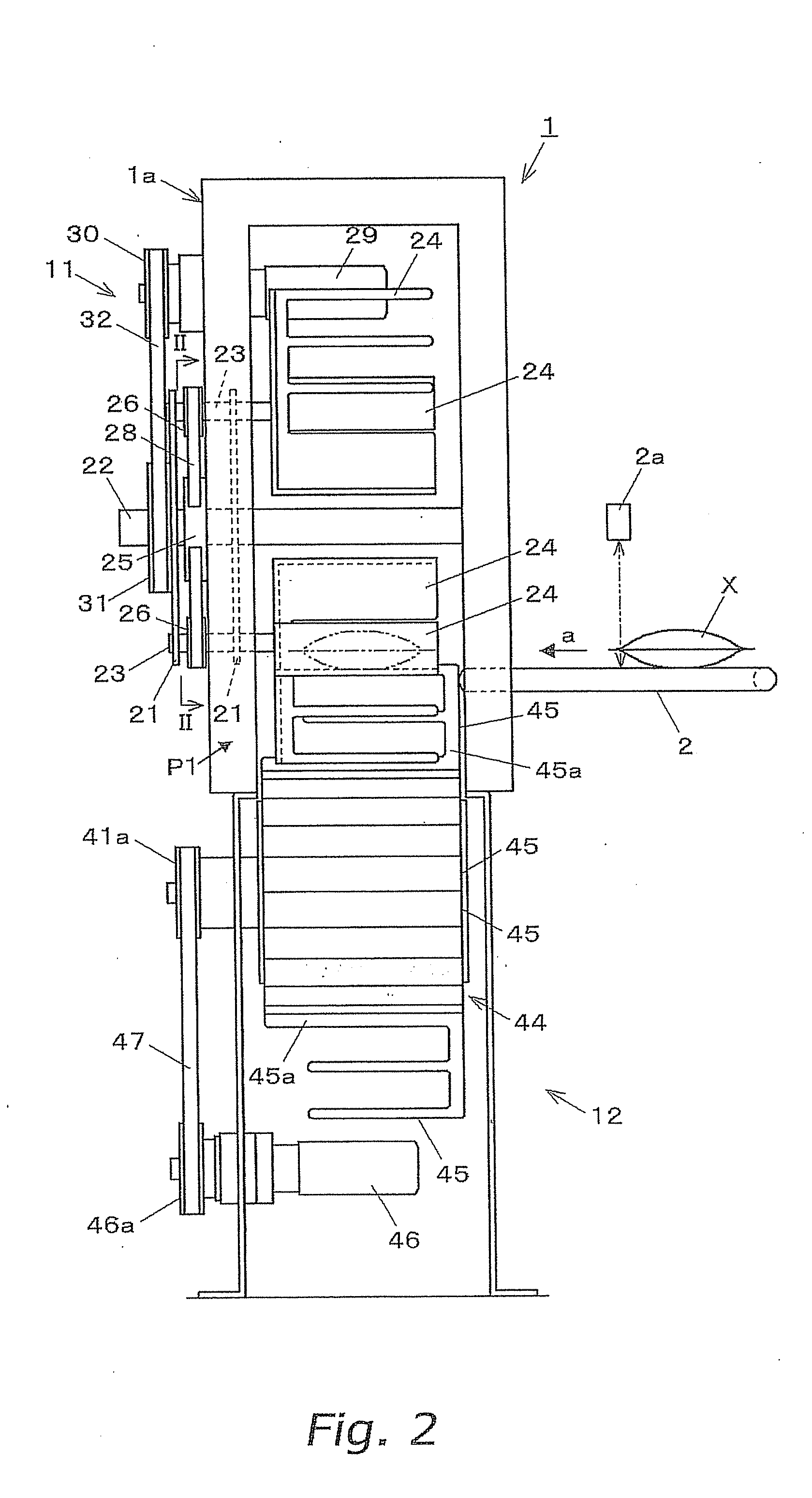
[0157] A conveyance apparatus 1 according to the first embodiment shown in FIGS. 1 and 2 is coupled to a carry-in conveyor 2. The carry-in conveyor 2 conveys, in an arrow “a” direction, a relatively flat packaged article X, such as snack foods and the like, which is supplied in a horizontal position from the upstream side. The conveyance apparatus 1 receives the article X from the carry-in conveyor 2, moves the article X to a standing position, accumulates a predetermined number of the articles X, and then conveys the same from a receiving point P1 to a discharging point P2 as shown by the arrow “b”. The conveyance apparatus 1 comprises, as main components, a delivery device 11 mounted to a main body case 1a and an accumulation and conveyance apparatus 12. Note that as shown in FIG. 2, a photoelectric thickness sensor 2a for measuring the thickness of each article X is provided above the carry-in conveyor 2.

[0158] The delivery device 11 receives the articles X one by one in the hor...

second embodiment

[0186] Next, a conveyance apparatus according to a second embodiment will be described. Note that in each embodiment and modified examples which are described below, components common or similar to the above-described components are denoted by the same reference numerals, so long as there is no confusion as to their identity.

[0187] As shown in FIG. 9, in this case, the rotation shafts 23 . . . 23, which are rotation support points of the four delivery tables 24 . . . 24 provided around the fixed shaft 22, are located in substantially the center of the delivery tables 24 . . . 24 (the length L1 is substantially equal to the length L2).

[0188] Accordingly, since the rotation shaft 23 of the delivery table 24 is located in substantially the center of the delivery table 24, the rotation radius R is the shortest, i.e., the centrifugal force F acting on the article X is the smallest, therefore demonstrating the preferable effect of preventing the article X from jumping out of the deliver...

third embodiment

[0189] Next, a conveyance apparatus according to a third embodiment will be described.

[0190] As shown in FIG. 10, in this case, the rotation shafts 23 . . . 23, which are rotation support points of the four delivery tables 24 . . . 24 provided around the fixed shaft 22 are located closer to a lower end portion of the delivery tables 24 . . . 24 in the standing position (the length L1 is shorter than the length L2).

[0191] The rotation shaft 23, which is the rotation support point of the delivery table 24, is located closer to the lower end portion of the delivery table 24 in the standing position. Consequently, for example, when the delivery table 24 is configured to rotate about the rotation shaft 23 in a clockwise direction as shown by the arrow “d” to change its position and simultaneously the delivery table 24 is configured to move around the fixed shaft 22 in a counterclockwise direction so as to move forward as shown by the arrow “c”, the delivery table 24 will move within a ...


PUM


Abstract

A conveyance apparatus is disclosed which includes a delivery device that delivers an article supplied in a horizontal position from a conveyor to an accumulation and conveyance apparatus, and delivery tables which receive the article and move the same to a standing position by rotating to the standing position, and which also deliver the article while orderly placing the same from front to rear in a bucket by moving forward; and a drive unit comprising a synchronous pulley, a synchronous timing belt, and a motor, which rotate and move the delivery tables in synchronization with the movement of the bucket. In addition, a rotation shaft, which is a rotation support point of the delivery table, is located above a lower end portion of the delivery table in the standing position.

Description

CROSS-REFERENCE TO RELATED APPLICATIONS [0001] This application claims priority to U.S. Provisional Patent Application No. 60 / 823,253, filed on Aug. 23, 2006, and Japan Patent Application Nos. 2005-332319 and 2005-335658. The entire disclosures of U.S. Provisional Patent Application No. 60 / 823,253 and Japan Patent Application Nos. 2005-332319 and 2005-335658 are hereby incorporated herein by reference.BACKGROUND OF THE INVENTION [0002] 1. Field of the Invention [0003] The present invention relates to the technical field of conveying articles, and more particularly to a conveyance apparatus configured to receive relatively flat articles at a receiving point, accumulate a predetermined number of the articles in a standing position, and deliver the articles to a discharging point. [0004] 2. Background Information [0005] Conventionally, in some cases, a predetermined number of packaged articles such as snack foods are accumulated in a predetermined position, and then packed in cardboard...

Claims


Application Information

Patent Timeline
IPC IPC(8): B65G47/24
CPCB65B35/243B65G29/02B65G47/846B65G47/252B65G47/082
Inventor SHIMOMAE, YOSHINOBUIWASA, SEISAKUKIMURA, TAKASHIYOKOTA, YUJI
Owner ISHIDA CO LTD
Why Eureka
Try Eureka