

Bead feeder
- Summary
- Abstract
- Description
- Claims
- Application Information
AI Technical Summary
Benefits of technology
Problems solved by technology
Method used
Image

Examples
first embodiment
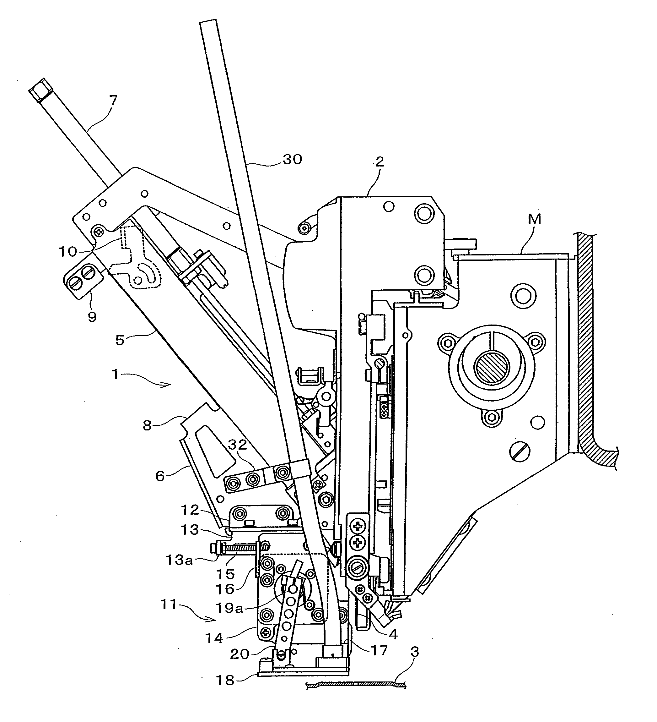
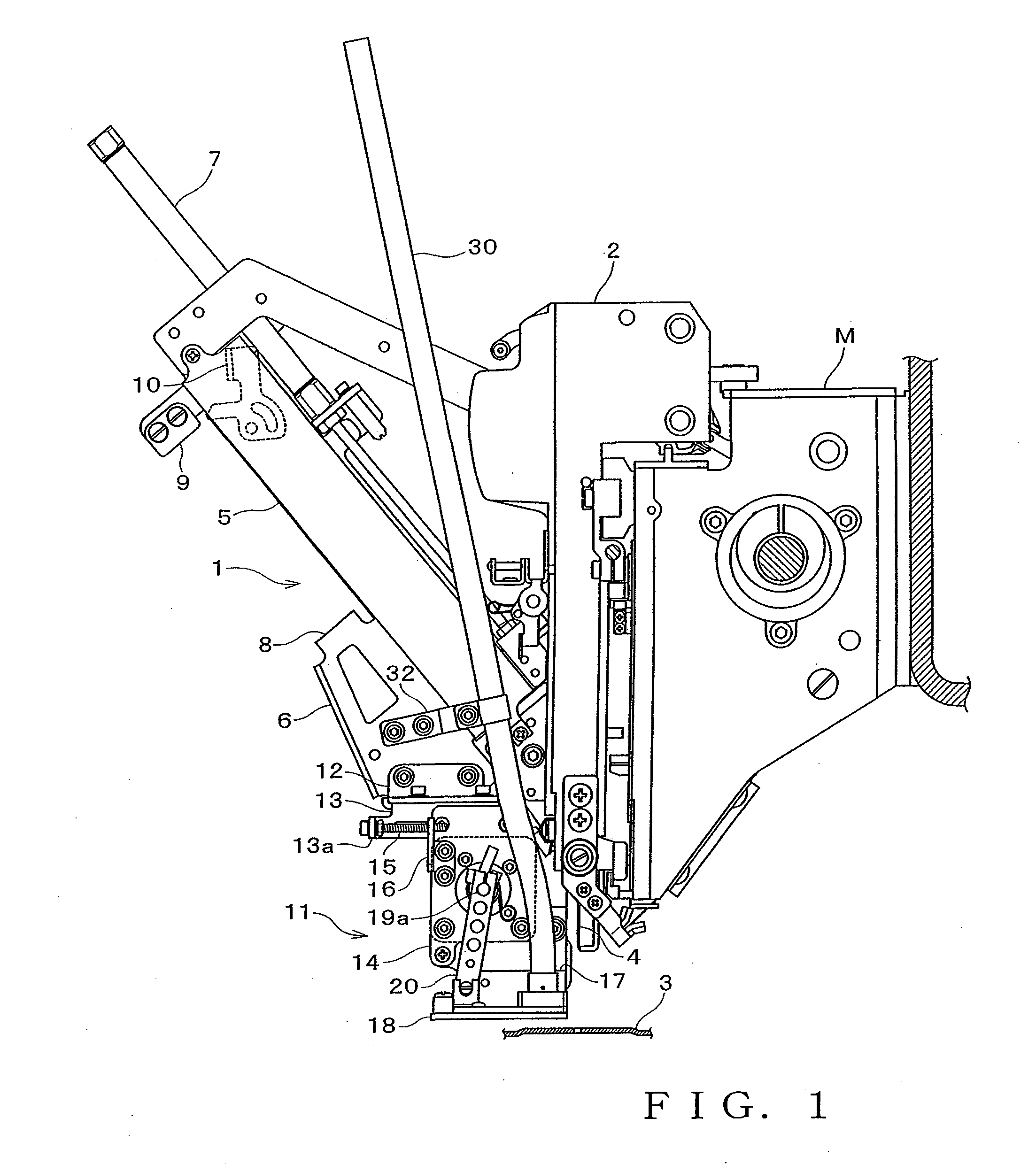
[0022]FIG. 1 is a right side view of a sewing machine equipped with a bead feeding unit (bead feeder) 1 according to a first embodiment of the present invention as viewed from the front right-hand side thereof. The sewing machine includes a machine head M, a needle bar case 2 and a needle plate 3. The needle bar case 2 shown here has a multi needle configuration including a plurality of sewing needles 4. The bead feeding unit 1 is adapted to be mounted to a left side surface and / or a right side surface of the needle bar case 2. The embodiment illustrates a sewing machine having the bead feeding unit 1 mounted only to the left side surface of the needle bar case 2. In a case where the bead feeding unit 1 is mounted to the left side surface of the needle bar case 2 as suggested by the embodiment, the leftmost one of the plural sewing needles 4 in the needle bar case 2 is used as a bead needle.
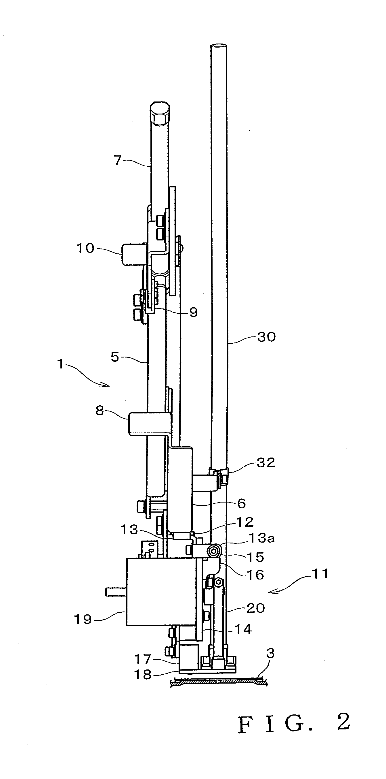
[0023]FIG. 2 is a front view showing the bead feeding unit 1. As shown in FIG. 1 and FIG. 2, ...
second embodiment
[0047]Next, description is made on a bead feeding mechanism according to another embodiment of the present invention. FIG. 10 is an exploded perspective view showing a bead feeding mechanism of a bead feeding unit according to a second embodiment of the present invention. In the figure, the same or similar reference numerals are used to refer to the same or similar components of the first embodiment described above. The bead feeding mechanism 38 shown in FIG. 10 has a different structure from that of the first embodiment. Specifically, the magnet 37 disposed on the bearing plate 18 is replaced by an elongate hole 39 extended in the direction of the forward / backward movement of the feed lever 23 while an engaging pin 40 engageable with the elongate hole 39 projects downward from the bottom surface of the support member 24 (the movement restricting member consisting of the elongate hole 39 and the engaging pin 40). Except for these, the bead feeding mechanism is constructed the same w...
PUM
 Abstract
Description
Claims
Application Information