Rotating disc aerator

Inactive Publication Date: 2014-11-13
ALENZI BADER SHAFAQA
View PDF3 Cites 3 Cited by
  • Summary
  • Abstract
  • Description
  • Claims
  • Application Information

AI Technical Summary

Benefits of technology

The present invention is a rotating disc aerator that is used to mix and aerate water. It includes a motorized base with two rods that extend from it, along with rotating discs that are locked to the rods and can slide back and forth along the shaft. The discs have absorbent material along their edges that can absorb air and water as they rotate. The central shaft and discs rotate simultaneously, while the discs reciprocate back and forth to compress and expand the absorbent material. This results in air and water being absorbed and expelled, resulting in efficient mixing and aeration of water. The invention can also include spray nozzles to wash contaminants from the absorbent material.

Problems solved by technology

Such systems are reasonably practical for relatively small aquaria and the like, but become quite costly in terms of initial cost and the cost of operation and maintenance when considering an installation in a relatively large body of water, such as a sewage treatment plant or the like.
Moreover, such systems are clearly not portable and cannot be temporarily installed in a natural body of water in response to a disaster, such as wastewater contamination, etc.

Method used


Image

  • Rotating disc aerator
  • Rotating disc aerator
  • Rotating disc aerator

Examples


first embodiment

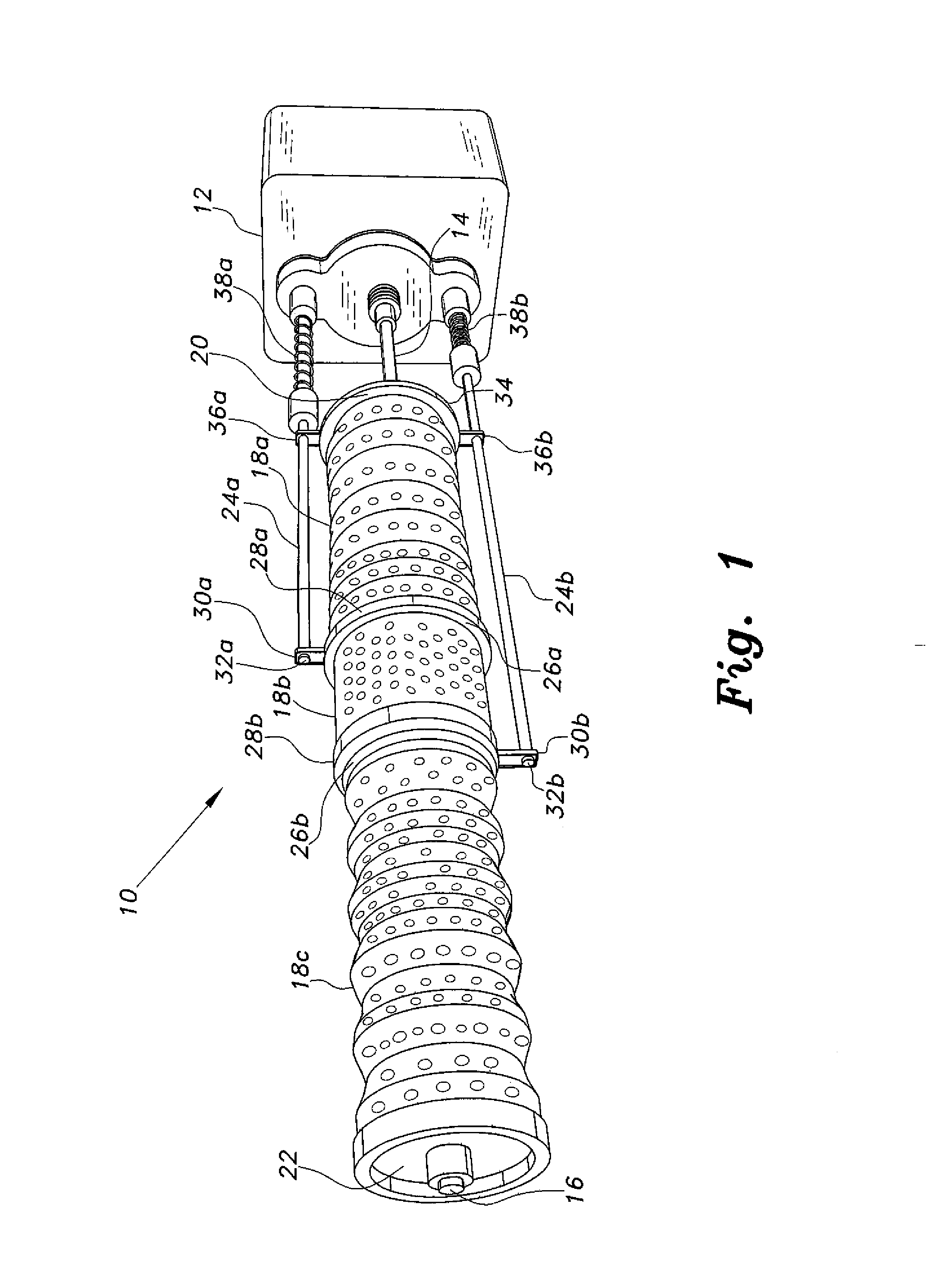
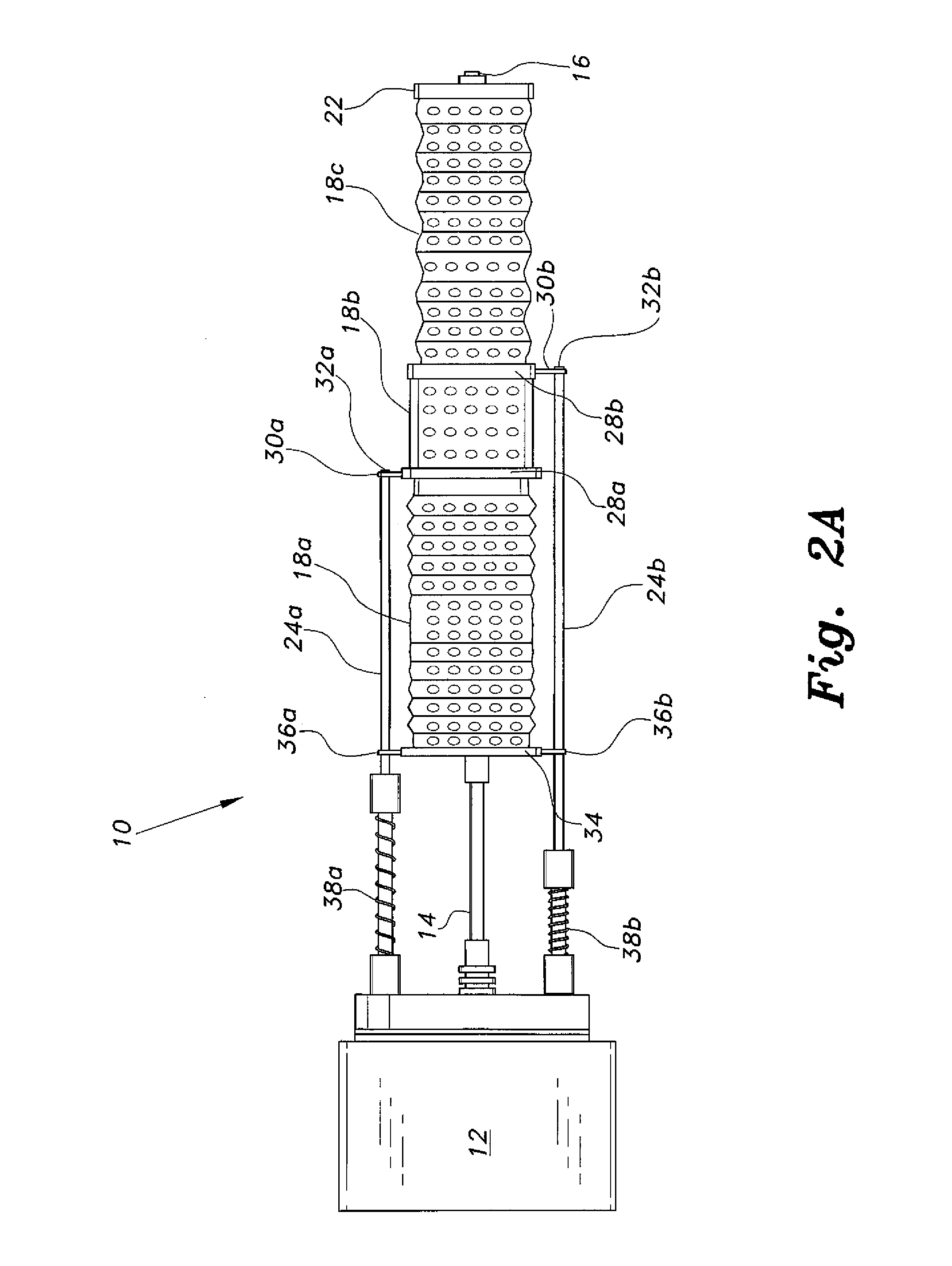
[0018]FIG. 1 of the drawings provides a perspective view of the rotating disc aerator 10, and FIGS. 2 and 3 provide side elevation views showing the reciprocating operation of the device to expand and contract the resilient open cell absorbent elements of the device. The aerator 10 includes a motorized body 12 containing conventional means for driving the moving components of the device (e.g., electric motor, etc.) and energy storage (e.g., electrical storage cells or battery, etc.) to provide power for the operation of the device. The motorized body 12 is sealed to provide a waterproof enclosure for the drive components therein, and is preferably provided with sufficient volume to provide buoyancy for that portion of the device. The motorized body 12 is preferably ballasted in order to maintain a constant orientation in the water, for reasons that will become apparent further below. This may be accomplished by placement of the electrical batteries in the lower portion of the body 1...
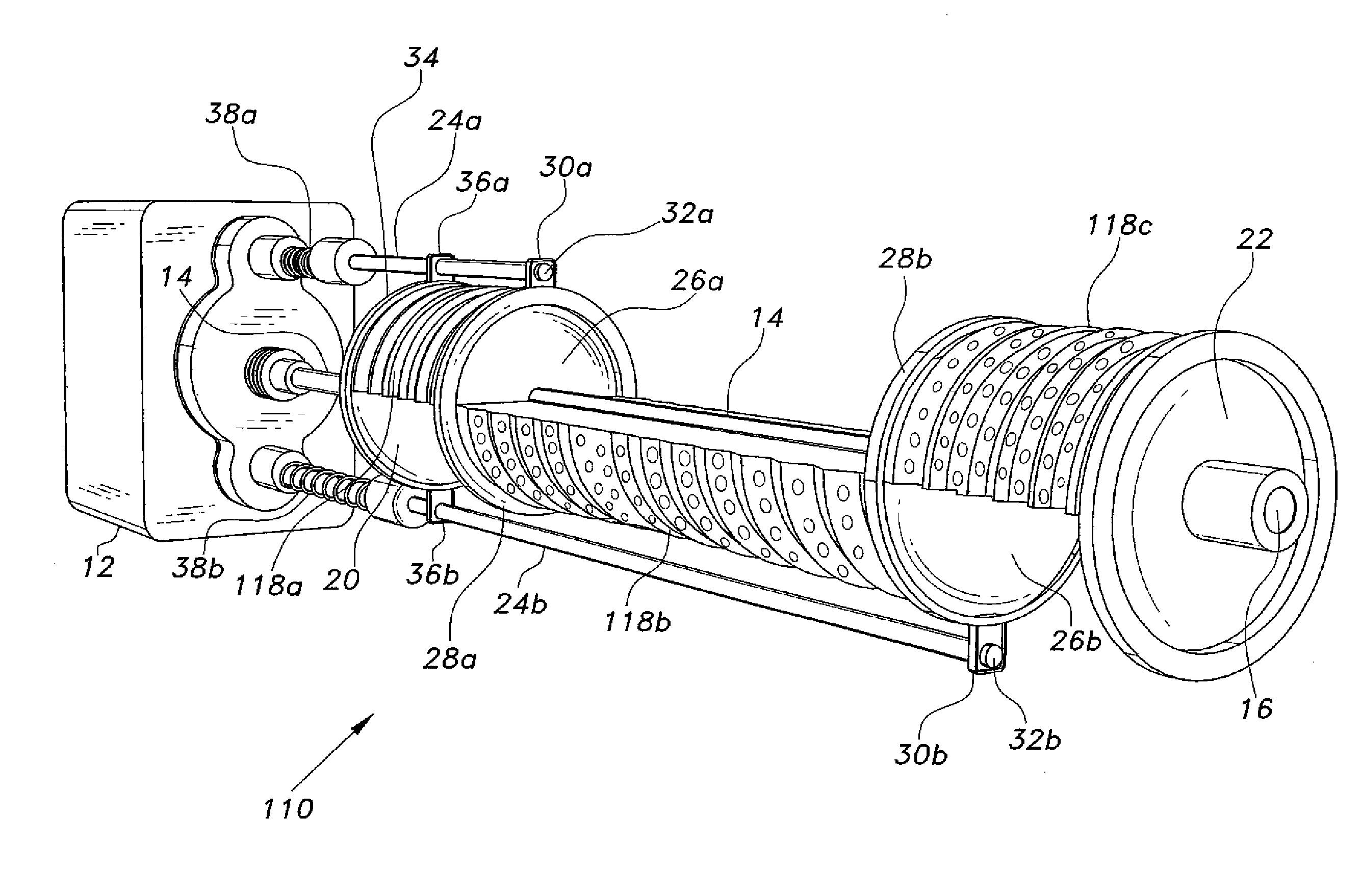
embodiment 110

[0029]FIG. 5 is an illustration of an additional embodiment, designated as rotating disc aerator 310. The aerator embodiment 310 combines features of the aerator 110 of FIG. 3 and the aerator 210 of FIG. 4. All of the components of the aerator 310 are identical to those corresponding components of the aerator 210 of FIG. 4, with the exception of the three absorbent elements 118a through 118c that are identical to those elements shown for the embodiment 110 of FIG. 3. The rotary and reciprocating operation of the device 310 is the same as that described above for the rotating disc aerator 210 of FIG. 4, the spray nozzles 42 beneath the spray guard 40 serving to wash or rinse contamination from the exposed absorbent elements 118a through 118c as they rotate above the water.


PUM

PropertyMeasurementUnit
Water absorptionaaaaaaaaaa

Abstract

The rotating disc aerator is a portable aeration device utilizing atmospheric air, rather than using a compressor for its air supply. The aerator includes a motorized base having a rotary shaft and diametrically opposed, oppositely reciprocating rods extending therefrom. A plurality of discs are disposed along the shaft and are connected to the ends of the rods. The discs are free to slide along the shaft as the rods reciprocate, but rotate with the shaft. A plurality of resilient absorbent elements (sponges, etc.) are installed along the rotary shaft between the discs. The aerator assembly is buoyant, about one-half of each absorbent element extending above the surface of the water when the aerator is placed therein. The upper portions of the absorbent elements absorb air as they rotate above the surface, and are compressed to expel the air into the water as they rotate beneath the water surface.

Description

BACKGROUND OF THE INVENTION[0001]1. Field of the Invention[0002]The present invention relates generally to water aeration devices, and particularly to a portable rotating disc aerator having a plurality of oppositely reciprocating resilient elements of open cell absorbent material disposed along a rotary shaft for absorbing air and dispensing the air beneath the surface of the water.[0003]2. Description of the Related Art[0004]Water is aerated for a wide variety of purposes, e.g., providing oxygenated water for aquarium use, introducing dissolved oxygen in water for aerobic bacteria in sewage processing, and other operations. Conventional aeration uses permanently installed, porous air pipes or ducts that are submerged within the body of water being treated. The air is supplied by adjacent compressors and expelled from the porous pipes to bubble up through the water. Such systems are reasonably practical for relatively small aquaria and the like, but become quite costly in terms of ...

Claims


Application Information

Patent Timeline
IPC IPC(8): B01F3/04
CPCB01F3/04531B01F3/04758B01F23/2342B01F27/053B01F27/054B01F33/503B01F33/86
Inventor ALENZI, BADER SHAFAQA
Owner ALENZI BADER SHAFAQA
Why Eureka
Try Eureka