Electrical bridge

a technology of electric bridges and electrical cables, which is applied in the direction of electrical apparatus casings/cabinets/drawers, electrical apparatus connection, casings/cabinets/drawers details, etc., can solve the problems of clutter of electrical cables to provide an electrical connection between two electronics racks of the same or different electronics racks, difficult installation of electrical cables between two electronic modules,

Active Publication Date: 2014-11-13
TE CONNECTIVITY CORP
View PDF5 Cites 20 Cited by
  • Summary
  • Abstract
  • Description
  • Claims
  • Application Information

AI Technical Summary

Benefits of technology

[0005]In one embodiment, an electrical bridge is provided for electrically connecting first and second electronic modules that include first and second external chassis, respectively. The electrical bridge includes a rigid housing extending along a fixed path from a first end to a second end, and first and second electrical contacts held by the housing. The first electrical contact is positioned at the first end of the housing. The second electrical contact is positioned at the second end of the housing. An electrical pathway is defined within the housing from the first electrical contact to the second electrical contact such that the first and second electrical contacts are electrically connected together. The first and second ends of the housing are configured to be mounted to the first and second external chassis, respectively, such that the first and second electrical contacts are configured to mate with, and thereby electrically connect to, the first and second electronic modules, respectively.
[0006]In an embodiment, an electronics rack includes a frame having first and second regions, and first and second electronic modules held by the frame within the first and second regions, respectively. The first and second electronic modules have first and second external chassis, respectively. The electronics rack includes an electrical bridge that electrically interconnects the first and second electronic modules. The electrical bridge includes a rigid housing extending along a fixed path from a first end to a second end, and first and second electrical contacts held by the housing. The first electrical contact is positioned at the first end of the housing. The second electrical contact is positioned at the second end of the housing. An electrical pathway is defined within the housing from the first electrical contact to the secon...

Problems solved by technology

But, electrical cables may be difficult to install between the two electronic modules, for example when there is a limited amount of space adjacent the electronics rack(s).
For example, the length of the electrical cable may snag and/or wrap around nearby structures (e.g., of the electronics rack(s), of the electronic modules held by the rack(s), etc.), which may interfere with the ability of a technician to neatly and/or efficiently route the electrical cable between the electronics modules.
Another disadvantage of using an electrical cable to provide an electrical connection between two electronics modules of the same or different electronics racks is clutter.
The clutter created by an electri...

Method used


Image

  • Electrical bridge
  • Electrical bridge
  • Electrical bridge

Examples


Embodiment Construction

[0016]The foregoing summary, as well as the following detailed description of certain embodiments will be better understood when read in conjunction with the appended drawings. As used herein, an element or step recited in the singular and proceeded with the word “a” or “an” should be understood as not excluding plural of said elements or steps, unless such exclusion is explicitly stated. Furthermore, references to “one embodiment” are not intended to be interpreted as excluding the existence of additional embodiments that also incorporate the recited features. Moreover, unless explicitly stated to the contrary, embodiments “comprising” or “having” an element or a plurality of elements having a particular property may include additional such elements not having that property.

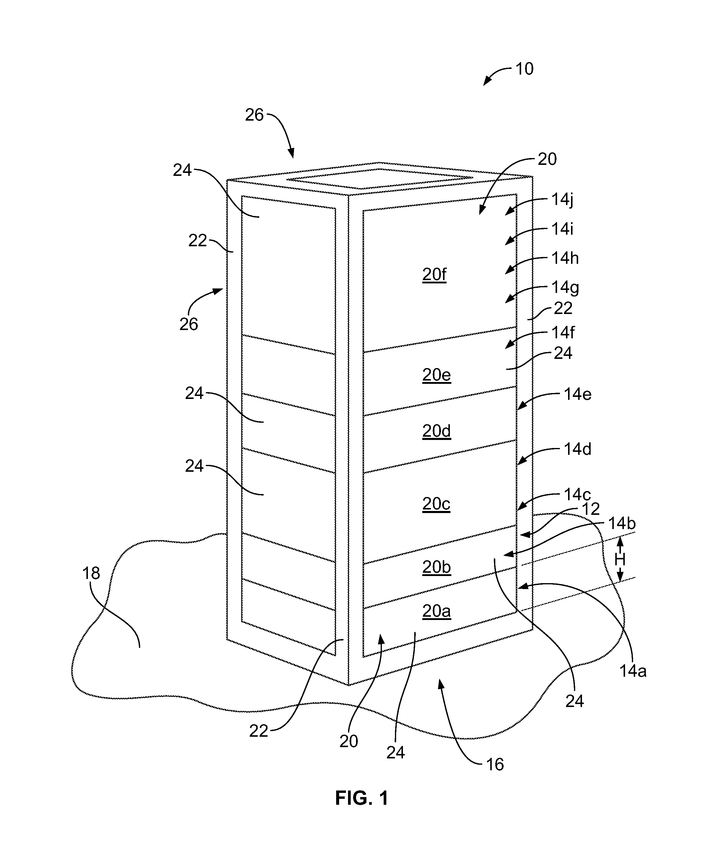
[0017]FIG. 1 is a perspective view of an exemplary embodiment of an electronics rack 10. The electronics rack 10 includes a frame 12 that is divided into a plurality of regions 14. In the illustrated embodiment,...


PUM


Abstract

An electrical bridge is provided for electrically connecting first and second electronic modules that include first and second external chassis, respectively. The electrical bridge includes a rigid housing extending along a fixed path from a first end to a second end, and first and second electrical contacts held by the housing. The first and second electrical contacts are positioned at the first and second ends, respectively, of the housing. An electrical pathway is defined within the housing from the first electrical contact to the second electrical contact such that the first and second electrical contacts are electrically connected. The first and second ends of the housing are configured to be mounted to the first and second external chassis, respectively, such that the first and second electrical contacts are configured to mate with, and thereby electrically connect to, the first and second electronic modules, respectively.

Description

BACKGROUND OF THE INVENTION[0001]The subject matter described herein relates generally to electrical bridges for electrically interconnecting two electronic modules in the same or different racks.[0002]Electronics racks are standardized enclosures that are used to hold a plurality of electronic modules, for example, servers, routers, processors, computers, databases, electrical power supplies, telecommunication equipment, control and / or automation equipment, audio and / or video equipment, and / or the like. Examples of standardized electronics racks include 19-inch racks (e.g., to accommodate electronic modules having front panels that are approximately 19 inches (482.6 mm) wide), 23-inch racks, 24-inch racks, and Open racks. An electronics rack includes a frame that is divided into a plurality of regions, which are typically arranged in a vertical column. The electronic modules are held by the frame within the regions. Each region has a standardized height of approximately 1.75 inches...

Claims


Application Information

Patent Timeline
IPC IPC(8): H01R31/08H05K5/02H01R13/6581
CPCH01R31/08H01R13/6581H05K5/0247H05K7/1492H05K9/0062H05K9/0098
Inventor NICHOLS, ROBERT PAULCOSTELLO, BRIAN PATRICK
Owner TE CONNECTIVITY CORP
Why Eureka
Try Eureka