Accelerator pedal device

Inactive Publication Date: 2014-11-20
TOYOTA JIDOSHA KK
View PDF9 Cites 8 Cited by
  • Summary
  • Abstract
  • Description
  • Claims
  • Application Information

AI Technical Summary

Benefits of technology

[0023]Therefore, the ease of assembling the

Problems solved by technology

However, as for the above-described accelerator pedal device, there is a possibility of the shaft portion slipping off from the fit-in portion d

Method used


Image

  • Accelerator pedal device
  • Accelerator pedal device
  • Accelerator pedal device

Examples


Example

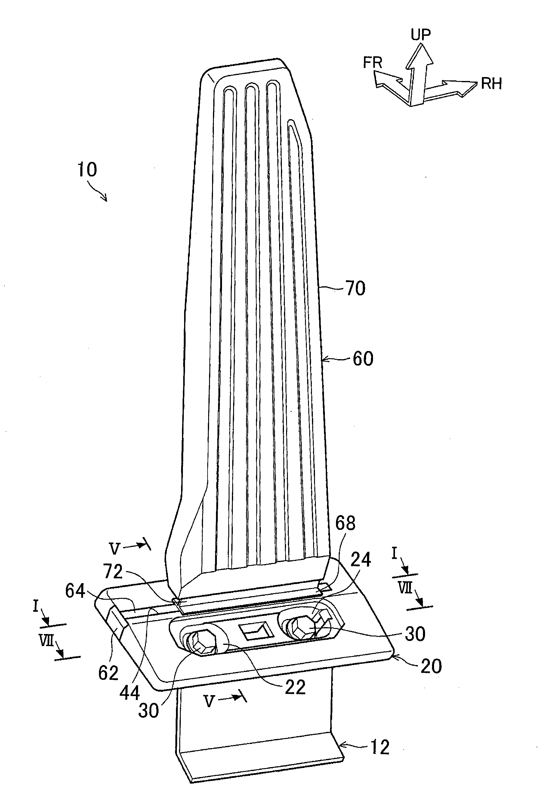
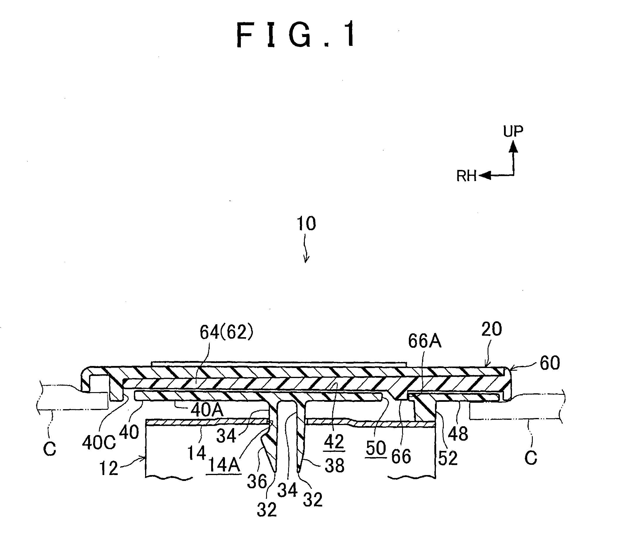
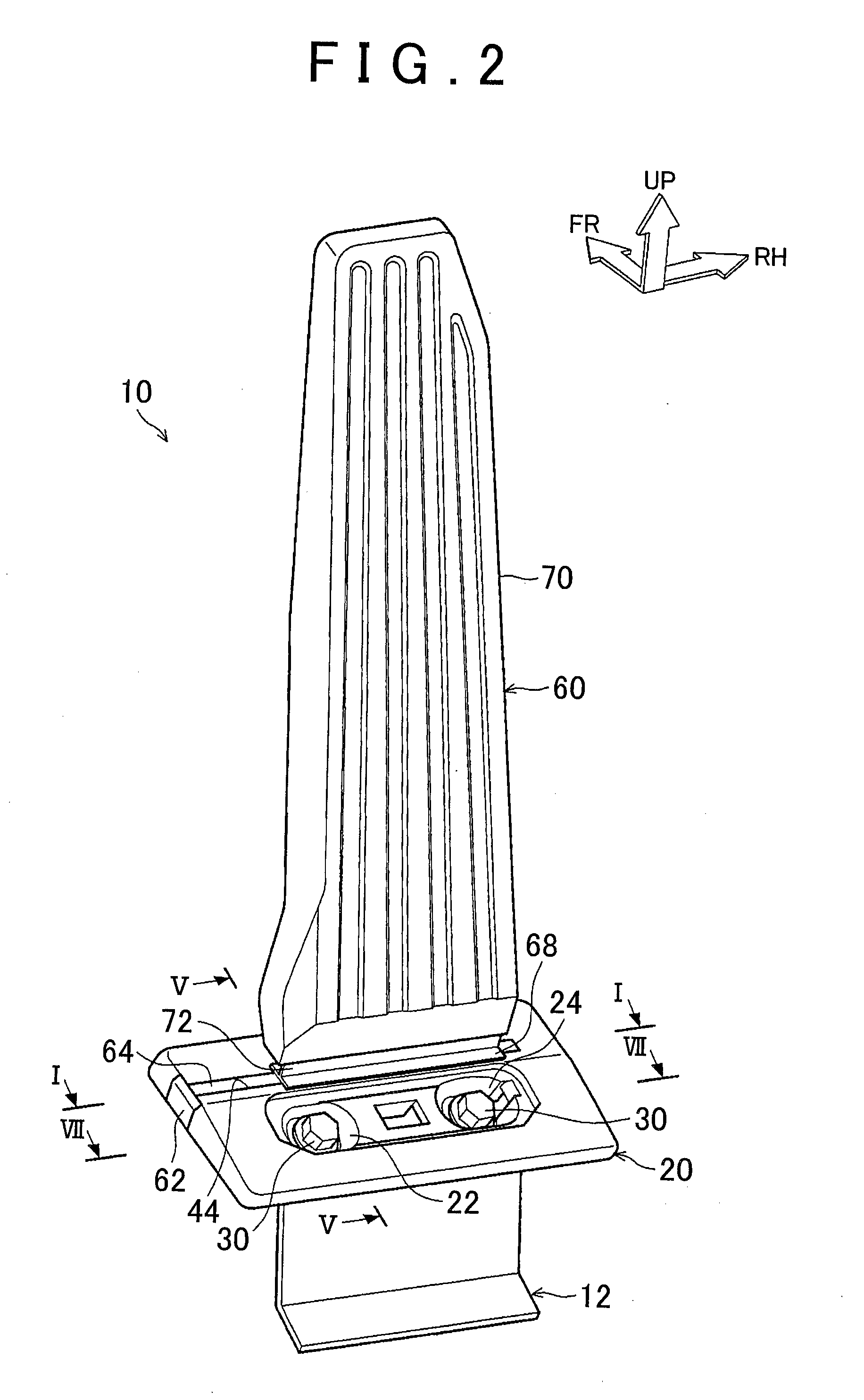
[0032]FIG. 2 shows the whole of an accelerator pedal device 10 in accordance with an embodiment of the invention in a perspective view. FIG. 3 shows a disassembled state of the accelerator pedal 10 in a perspective view. Furthermore, FIG. 5 shows the accelerator pedal device 10 in a sectional view taken from a leftward direction of the vehicle. It is to be noted that arrows FR appropriately shown in the drawings indicate the forward direction of the vehicle. An arrow RH shows a rightward direction of the vehicle (a direction to one of the sides in the vehicle width direction). An arrow UP indicates an upward direction of the vehicle.

[0033]As shown in FIGS. 2, 3 and 5, the accelerator pedal device 10 includes a bracket 12, a mount 20 and a pedal 60. The bracket 12 is fixed to a floor F on which a driver's seat of the vehicle is provided. The mount 20 is fastened (assembled) to the bracket 12. The pedal 60 is supported on the mount 20. It is to be noted that in FIG. 3, illustration of...


PUM


Abstract

In an accelerator pedal device, a fitted portion of a pedal is inserted into a groove portion of a fitting portion by sliding the fitted portion, and then the fitted portion and the groove portion are fitted to each other. Furthermore, an engagement hook portion of the fitted portion is engaged with an engagement hole. Still further, an upper wall of the bracket contacts a stopper portion of the mount, so that the engagement hole is restrained from being displaced in a direction away from the fitted portion.

Description

BACKGROUND OF THE INVENTION[0001]1. Field of the Invention[0002]The invention relates to an accelerator pedal device.[0003]2. Description of the Related Art[0004]In an accelerator pedal device described in Japanese Utility Model Application Publication No. 6-12160 (JP 6-12160 U), a support member (mount) is provided on a floor. This support member (mount) is constructed of a pair of spring plates that form a fit-in opening and a fit-in portion.[0005]Then, a shaft portion of the accelerator pedal is pressed in to the fit-in portion side from the fit-in opening. As a result, the spring plates elastically deform so that the shaft portion is engaged with the fit-in portion. On the other hand, the shaft portion engaged with the fit-in portion is drawn to the fit-in opening side. As a result, the spring plates elastically deform so that the shaft portion is detached from the fit-in portion (the engagement between the shaft portion and the fit-in portion is released). Thus, the accelerator...

Claims


Application Information

Patent Timeline
IPC IPC(8): G05G1/44
CPCG05G1/44G05G1/30Y10T74/20534
Inventor YOKOI, YOSHIMITSUFUKAYA, YUKO
Owner TOYOTA JIDOSHA KK
Why Eureka
Try Eureka