Bicycle sprocket and bicycle crank assembly

a technology of bicycle sprocket and crank assembly, which is applied in the direction of mechanical equipment, transportation and packaging, hoisting equipment, etc., can solve the problems of complicated shifting action, and achieve the effect of easy shifting action

Active Publication Date: 2014-11-20
SHIMANO INC
View PDF22 Cites 99 Cited by
  • Summary
  • Abstract
  • Description
  • Claims
  • Application Information

AI Technical Summary

Benefits of technology

[0038]The first sprocket may have at least one shifting area. In this case, the shifting action on the first sprocket can be performed readily even though the first sprocket is designed so that the chain can be held stably during the normal pedaling action.
[0039]The second sprocket may have at least one shifting area. In this case, the shifting action on the second sprocket can be performed readily even though the second sprocket is designed so that the chain can be held stably during the normal pedaling action.
[0040]The third sprocket may have at least one

Problems solved by technology

Therefore, when a sprocket having teeth that have different axial widths is employed in a convention

Method used


Image

  • Bicycle sprocket and bicycle crank assembly
  • Bicycle sprocket and bicycle crank assembly
  • Bicycle sprocket and bicycle crank assembly

Examples


second embodiment

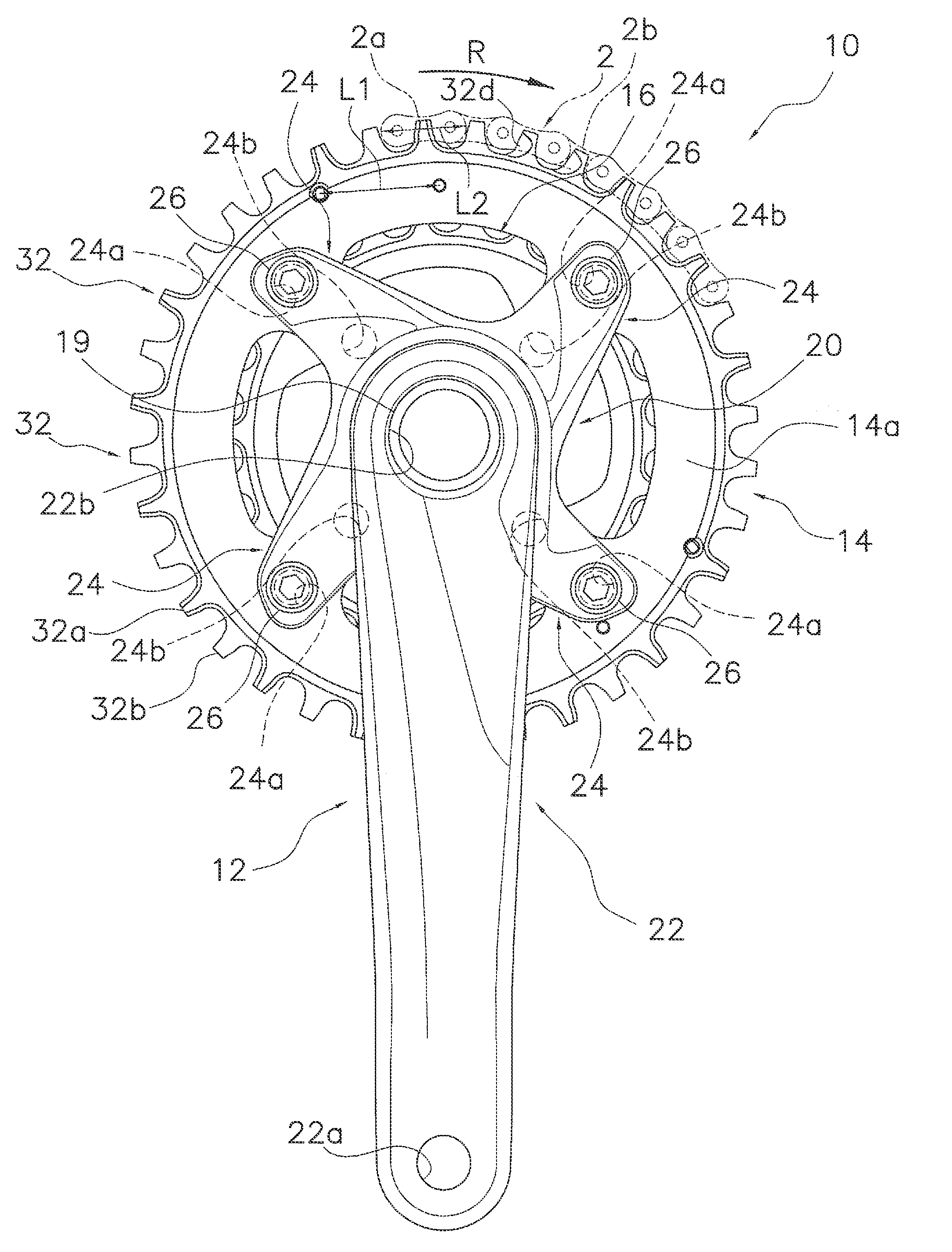
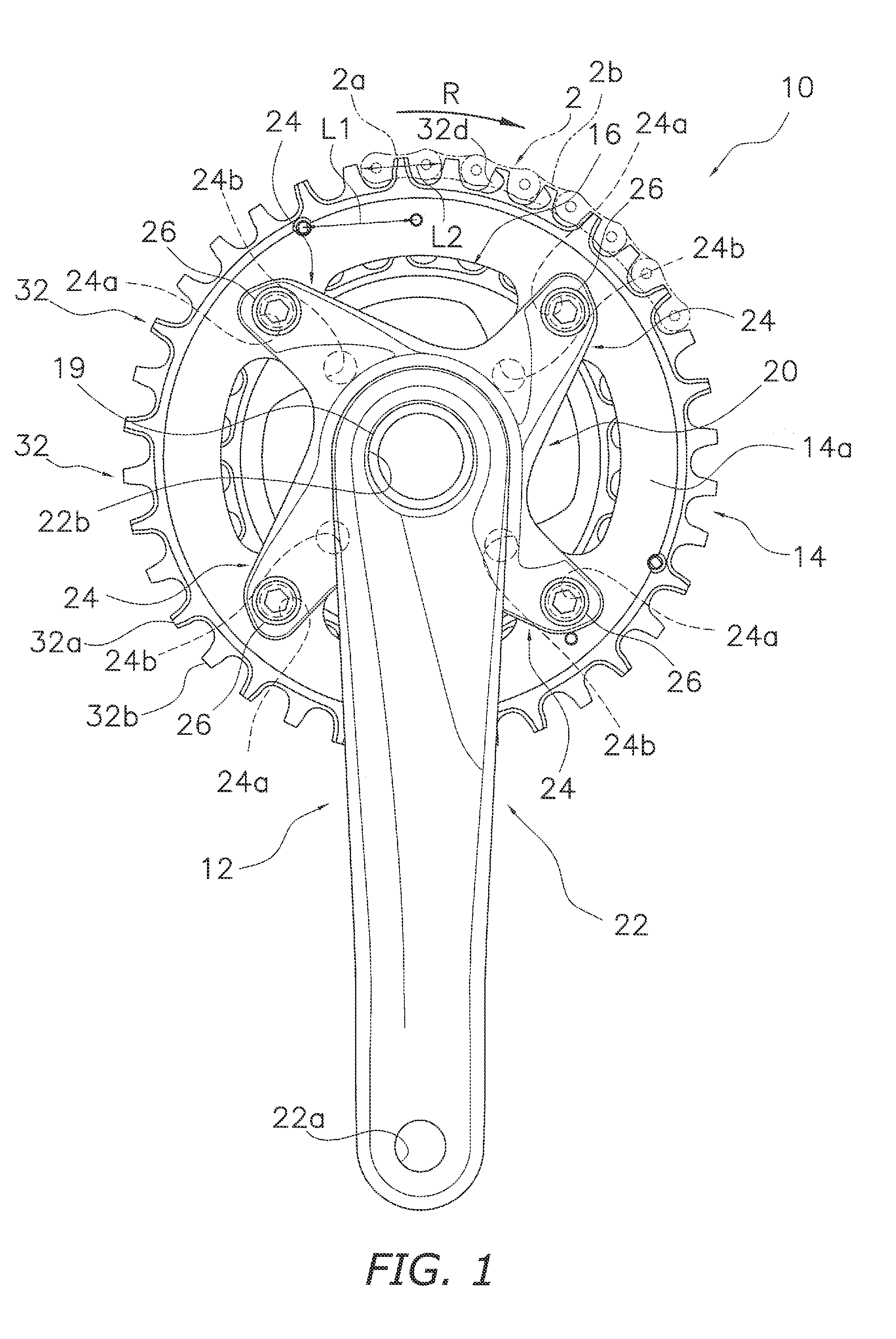
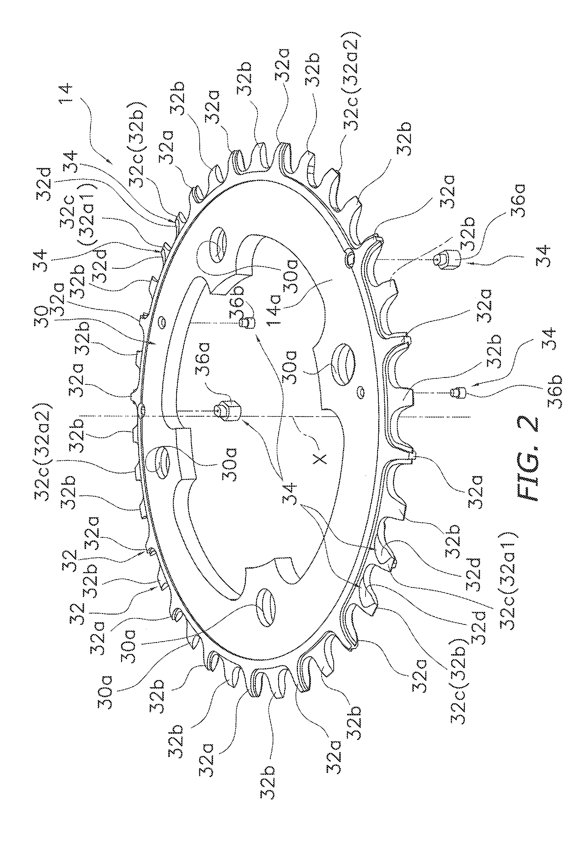
[0079]In the first embodiment, the bicycle crank assembly 10 has a first sprocket 14 and a second sprocket 16, but the crank assembly 110 of the second embodiment further comprises a third sprocket 18 in addition to the first sprocket 14 and the second sprocket 16, as shown in FIG. 7. The third sprocket 18 has fewer teeth than the second sprocket 16. The first sprocket 14 and the second sprocket 16 have the same configurations as the first embodiment and are therefore denoted in FIG. 7 by the same symbols and are not described.

[0080]Third Sprocket

[0081]The third sprocket 18 has a rotational center axis Z, and comprises a third sprocket main body 50, a plurality (e.g. 20 to 30) of teeth 52 disposed along the circumferential direction on the radially outer side of the third sprocket main body 50, and a third shifting area 54, as shown in FIG. 8. The third sprocket main body 50 is an example of a sprocket main body. The third shifting area 54 is an example of a shifting area. The third...


PUM


Abstract

A first sprocket is capable of engaging with a chain. The first sprocket has a first sprocket main body, a plurality of teeth disposed along a circumferential direction on the radially outer side of the first sprocket main body, and at least one shifting area. The teeth include at least one first tooth having a first maximum axial width and at least one second tooth having a second maximum axial width. The first maximum axial width is greater than the second maximum axial width. The first tooth is formed to be capable of engaging with an outer link plate of the chain. The second tooth is formed to be capable of engaging with an inner link plate of the chain.

Description

CROSS-REFERENCE TO RELATED APPLICATIONS[0001]This application claims the benefit of U.S. Provisional Application No. 61 / 824,568, filed on May 17, 2013. The entire disclosure of U.S. Provisional Application No. 61 / 824,568 is hereby incorporated herein by reference.BACKGROUND[0002]1. Field of the Invention[0003]This invention generally relates to a bicycle sprocket and a bicycle crank assembly comprising the bicycle sprocket.[0004]2. Background Information[0005]Bicycle sprockets are provided both to a crank assembly located in the middle of a bicycle and to the rear wheel, and the rotation of the crank assembly is transmitted to the rear wheel by a chain meshed with the sprockets. In a bicycle chain, an inner link plate and an outer link plate are linked alternately; therefore, when the teeth of the sprockets have the same thickness, the gaps between the outer link plate and the teeth of the sprockets are larger than the gaps between the inner link plate and the teeth of the sprockets...

Claims


Application Information

Patent Timeline
IPC IPC(8): F16H55/30B62M1/36
CPCB62M1/36F16H55/30B62M9/00B62M9/04B62M9/105Y10T74/2165B62M9/10
Inventor SUGIMOTO, AKINOBUHIROSE, YUKI
Owner SHIMANO INC
Why Eureka
Try Eureka