
Spring controlled valve

a technology of springs and valves, applied in the direction of valves, mechanical equipment, transportation and packaging, etc., can solve the problem that none of these valves, however, use spring coils, etc., and achieve the effect of increasing the resistance to gas flow

Active Publication Date: 2014-11-20
PROPORTIONAIR INCORPORATED
View PDF14 Cites 4 Cited by
  • Summary
  • Abstract
  • Description
  • Claims
  • Application Information

AI Technical Summary

Benefits of technology

The present disclosure describes a back-pressure regulator for a gas supply system. The regulator has a housing with two openings and a spring that can move to allow gas to flow between the openings. The housing also has a connecting portion for attaching a conduit and an O-ring to prevent gas leakage. The actuator has a piston and a plate, and it can move to allow gas to flow between the openings. The spring has a central opening and is coated with a resilient material to seal it when compressed. The technical effect of the invention is to provide a reliable and efficient back-pressure regulator for gas supply systems.

Problems solved by technology

None of these valves, however, use the coils of a spring to control the flow of gas through the valve and, in certain embodiment, to set various valve parameters as a function of a constant of the spring.

Method used


Image

  • Spring controlled valve
  • Spring controlled valve
  • Spring controlled valve

Examples


Embodiment Construction

[0025]For the purposes of promoting an understanding of the principles of the disclosure, reference will now be made to the embodiments illustrated in the drawings, which are described below. The embodiments disclosed below are not intended to be exhaustive or limit the invention to the precise form disclosed in the following detailed description. Rather, the embodiments are chosen and described so that others skilled in the art may utilize their teachings. It will be understood that no limitation of the scope of the disclosure is thereby intended. The disclosure includes any alterations and further modifications in the illustrated devices and described methods and further applications of the principles of the disclosure which would normally occur to one skilled in the art to which the disclosure relates.

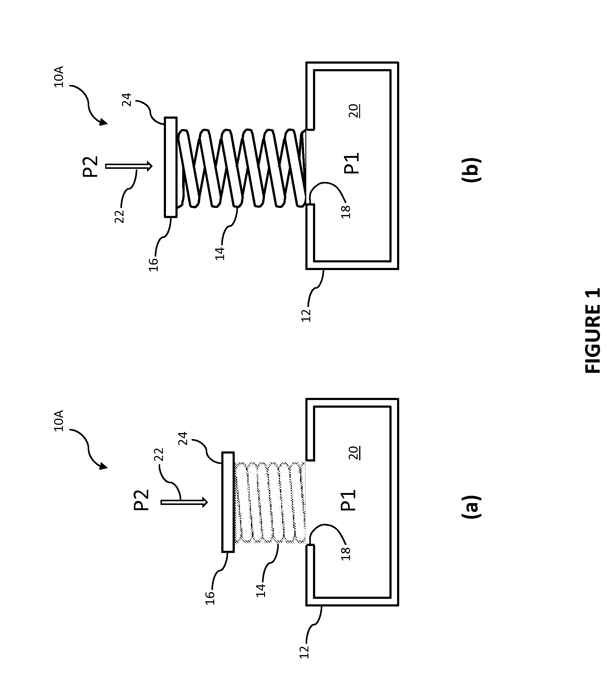
[0026]Referring now to FIGS. 1(a)-(b), a basic embodiment of a spring controlled valve according to the principles of the present disclosure is shown. In this embodiment, valve 10A ...


PUM


Abstract

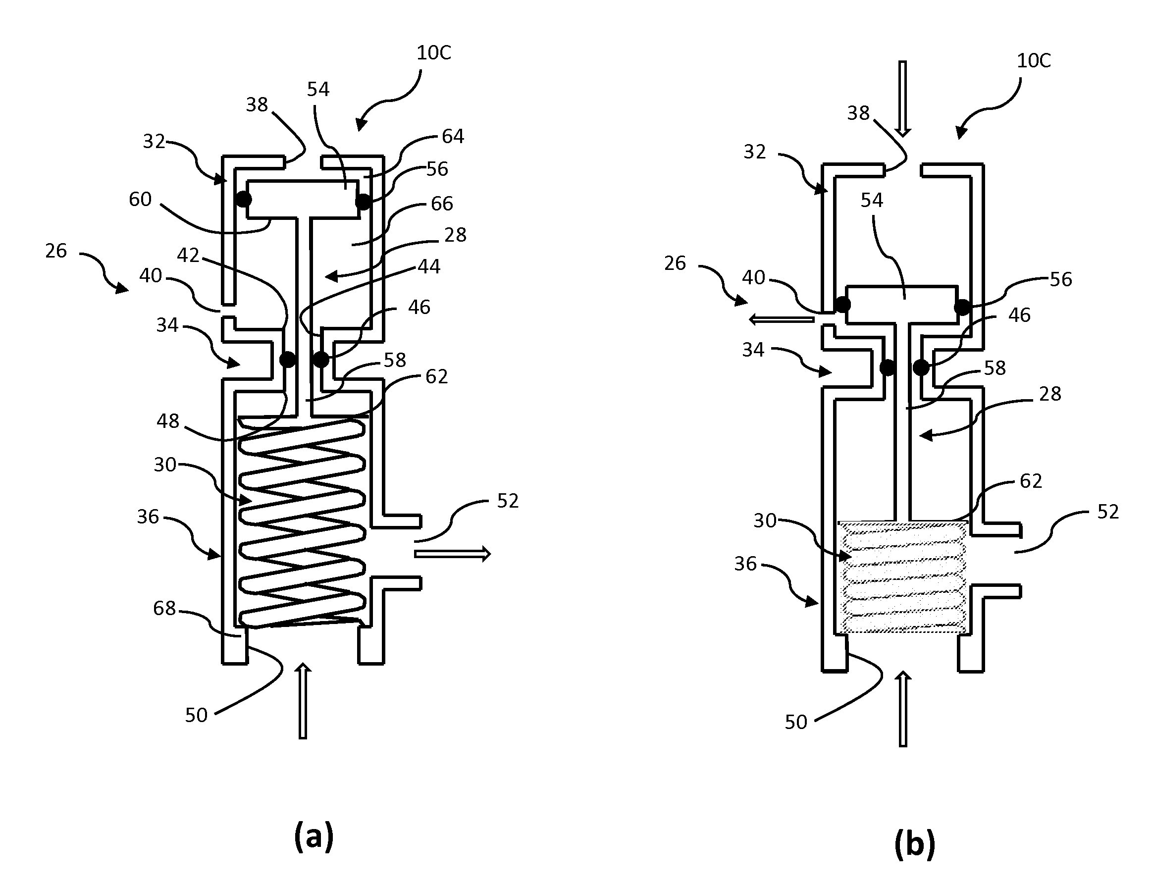
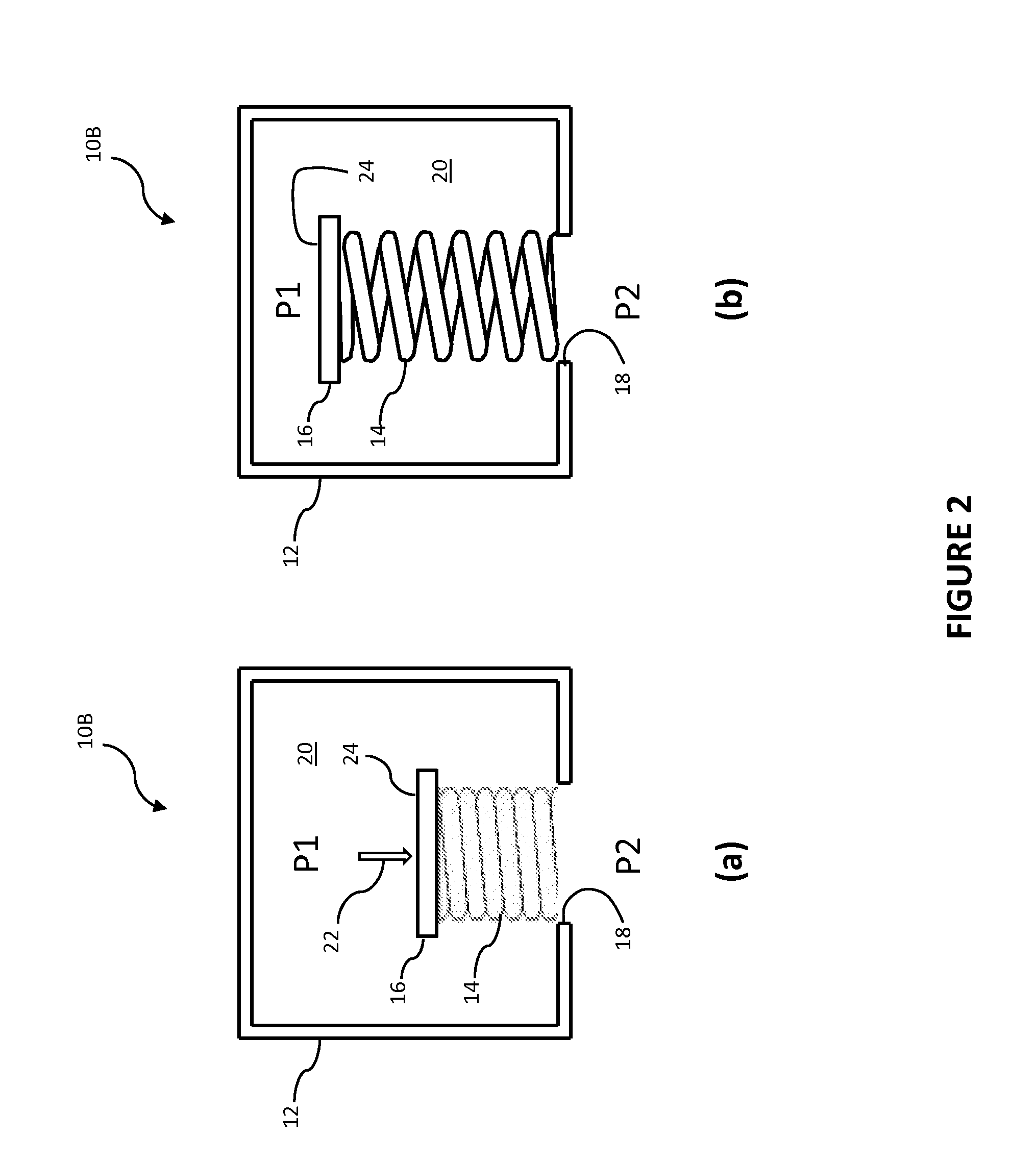
The present disclosure provides a spring controlled valve including a spring being movable between an expanded position wherein coils of the spring are spaced apart from one another thereby permitting gas flow through the valve and a compressed position wherein the coils are in contact with one another thereby substantially preventing gas flow through the valve.

Description

FIELD OF THE DISCLOSURE[0001]The present disclosure relates to a spring controlled valve, and more particularly to a valve wherein the flow through and / or pressure drop across a chamber is a function of the spring constant of a spring used to influence the flow and / or pressure drop across the chamber.BACKGROUND OF THE DISCLOSURE[0002]It is desirable to control the flow and / or pressure of gas or fluids for various purposes. Many different types of valves are known. None of these valves, however, use the coils of a spring to control the flow of gas through the valve and, in certain embodiment, to set various valve parameters as a function of a constant of the spring.SUMMARY OF THE DISCLOSURE[0003]In one exemplary embodiment of the present disclosure, a valve for controlling gas flow is provided. The valve includes a spring having a central opening, a first end connected to an opening into an interior of an enclosure to permit gas flow from the interior to the central opening, and a se...

Claims


Application Information

Patent Timeline
Patent Type & Authority Applications(United States)
IPC IPC(8): G05D16/10
CPCG05D16/10F16K1/40Y10T137/7793
Inventor COOK, DAN
Owner PROPORTIONAIR INCORPORATED
Learn More