Heat dissipating system

a heat dissipating system and heat dissipation technology, applied in the direction of machines/engines, positive displacement liquid engines, lighting and heating apparatus, etc., can solve the problems of difficult adaptation of conventional fans with blades to thinner electronic products, and the heat dissipation efficiency of the system becomes lower, so as to reduce the turbulence of flow and increase the cooling effect.

Active Publication Date: 2014-11-20
ASUSTEK COMPUTER INC
View PDF6 Cites 3 Cited by
  • Summary
  • Abstract
  • Description
  • Claims
  • Application Information

AI Technical Summary

Benefits of technology

[0010]Base on the descriptions above, in the heat dissipating system, the air inlet and the air outlet of the piezoelectric fan will not interfere with each other

Problems solved by technology

However, a conventional fan with blades is difficult to be adapted to the thinner electronic product.
However, since the heat dissipating system is sealed, the whole environment temperature in th

Method used


Image

  • Heat dissipating system
  • Heat dissipating system
  • Heat dissipating system

Examples


Embodiment Construction

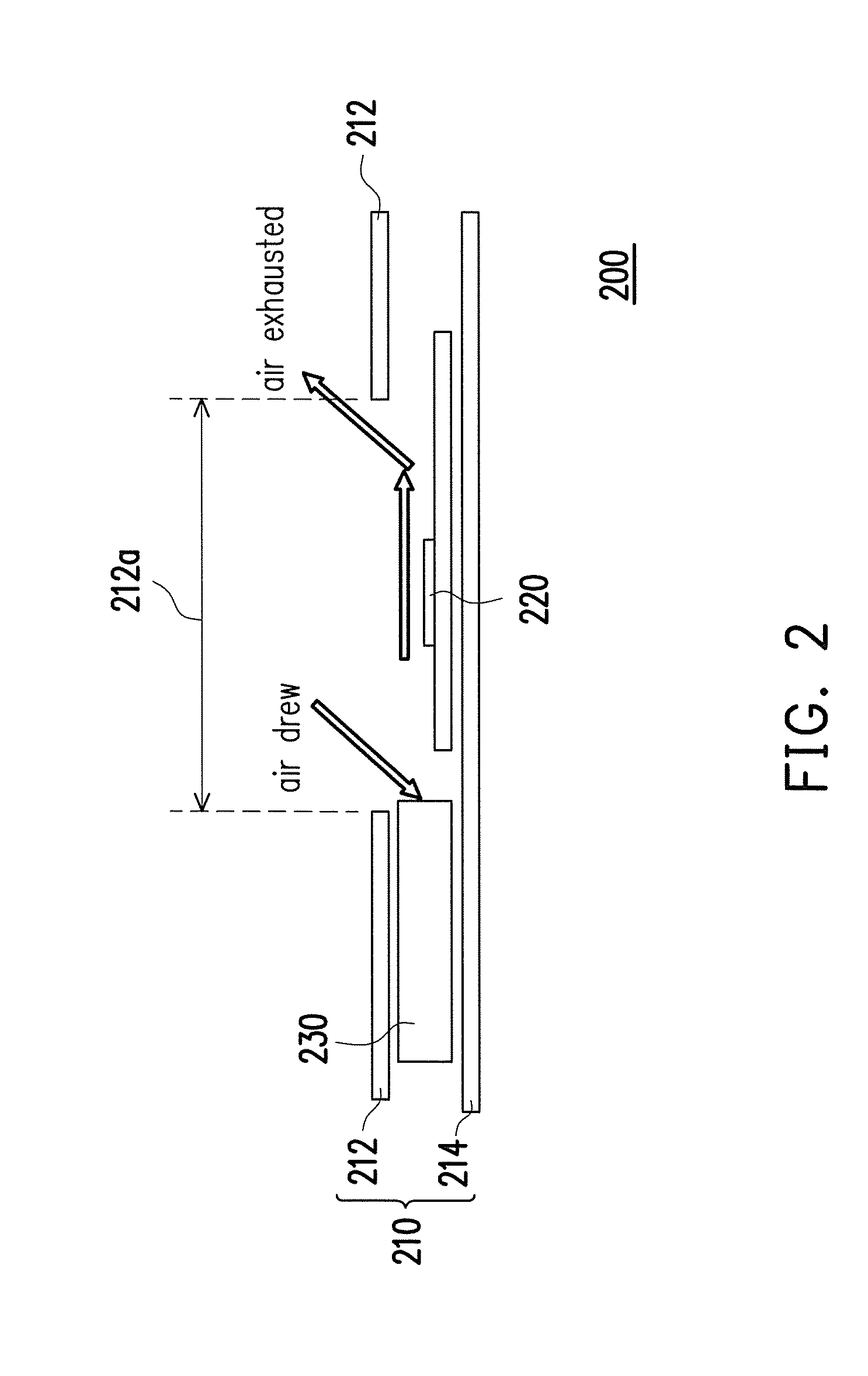
[0017]FIG. 2 is a schematic diagram showing a heat dissipating system in an embodiment. As shown in FIG. 2, the heat dissipating system 200 includes a casing body 210, a heat source 220 and a piezoelectric fan 230. The material of the casing body 210 may be plastic which is not limited herein. The casing body 210 has an upper casing 212 and a bottom casing 214. In the embodiment, the upper casing 212 has an air inlet 212a. The heat source 220 and the piezoelectric fan 230 are both disposed in the casing body 210. The piezoelectric fan 230 has an opening 232 facing the piezoelectric fan 230, and the air inlet 212a is adjacent to the opening 232 of the piezoelectric fan 230.

[0018]FIG. 3 is a schematic diagram showing that a piezoelectric fan of a heat dissipating system operates in an embodiment. As shown in FIG. 2 and FIG. 3, the casing body 210 has multiple side walls 261 surrounding the periphery of the upper casing 212 and the bottom casing 214. Furthermore, the heat source 220 fa...


PUM


Abstract

A heat dissipating system including a casing body, a heat source and a piezoelectric fan is provided. The casing body includes an upper casing and a bottom case, wherein at least one of the upper casing and the bottom casing includes at least one air inlet. The heat source and the piezoelectric fan are both disposed in the casing body. The piezoelectric fan has an opening facing the heat source while the air inlet is adjacent to the opening. Air is adsorbed into the opening through the air inlet and is exhausted out towards a direction of the heat source by the piezoelectric fan.

Description

CROSS-REFERENCE TO RELATED APPLICATION[0001]This application claims the priority benefit of TW application serial No. 102117397, filed on May 16, 2013. The entirety of the above-mentioned patent application is hereby incorporated by reference herein and made a part of specification.BACKGROUND OF THE INVENTION[0002]1. Field of the Invention[0003]The invention is relates to a heat dissipating system and, more particularly, to a heat dissipating system for an electronic device.[0004]2. Description of the Related Art[0005]As the electronic device becomes thinner and lighter, an active heat dissipating system is used to the electronic device to improve the CPU efficiency to avoid the electronic device overheated. However, a conventional fan with blades is difficult to be adapted to the thinner electronic product. Thus, fans with vibrating membranes using piezoelectric materials or electromagnetic induction instead of blades are developed.[0006]In a conventional heat dissipating system, p...

Claims


Application Information

Patent Timeline
IPC IPC(8): H05K7/20F04B45/04F04B43/04
CPCH05K7/20172H05K2007/20018F04B45/045F04B43/046F04B45/047F04F7/00
Inventor YEN, CHANG-HSULIN, CHIEN-YU
Owner ASUSTEK COMPUTER INC
Why Eureka
Try Eureka