Method for High-Resolution 3D Localization Microscopy

a localization microscopy and high-resolution technology, applied in the field of high-resolution 3d localization microscopy, can solve the problems of distortion of the image of the fluorescing fluorescence marker, no useful resolution inside the overlap region, and the need to capture twice the number, so as to minimize the illumination the complexity of the calculation for the localization of the fluorescence marker should be kept as low, and the resolution is high.

Inactive Publication Date: 2014-11-20
CARL ZEISS MICROSCOPY GMBH
View PDF1 Cites 7 Cited by
  • Summary
  • Abstract
  • Description
  • Claims
  • Application Information

AI Technical Summary

Benefits of technology

[0017]Therefore, the problem addressed by the invention is that of providing a method for PAL microscopy which enables three-dimensional high resolution, and minimizes the illum...

Problems solved by technology

The disadvantage of this approach is that it is necessary to capture twice the number of still images for the localization—particularly for each light sheet position—than would be required in conventional PALM imaging.
Finally, there can generally be no useful resolution inside the region of overlap which is filtered out.
A disadvantage of this method is that, where a molecular dipole is present, the local environment and orientation thereof can lead to distortion of the image of the fluorescing fluorescence marker, and this distortion nevertheless has nothing to do with the depth position.
In PAL microscopy, an undesirable illumination of the fluorescence mark...

Method used


Image

  • Method for High-Resolution 3D Localization Microscopy
  • Method for High-Resolution 3D Localization Microscopy
  • Method for High-Resolution 3D Localization Microscopy

Examples


Embodiment Construction

[0038]Elements which correspond functionally or structurally in the different figures are indicated with the same reference numbers throughout, in order to avoid repetition in the description.

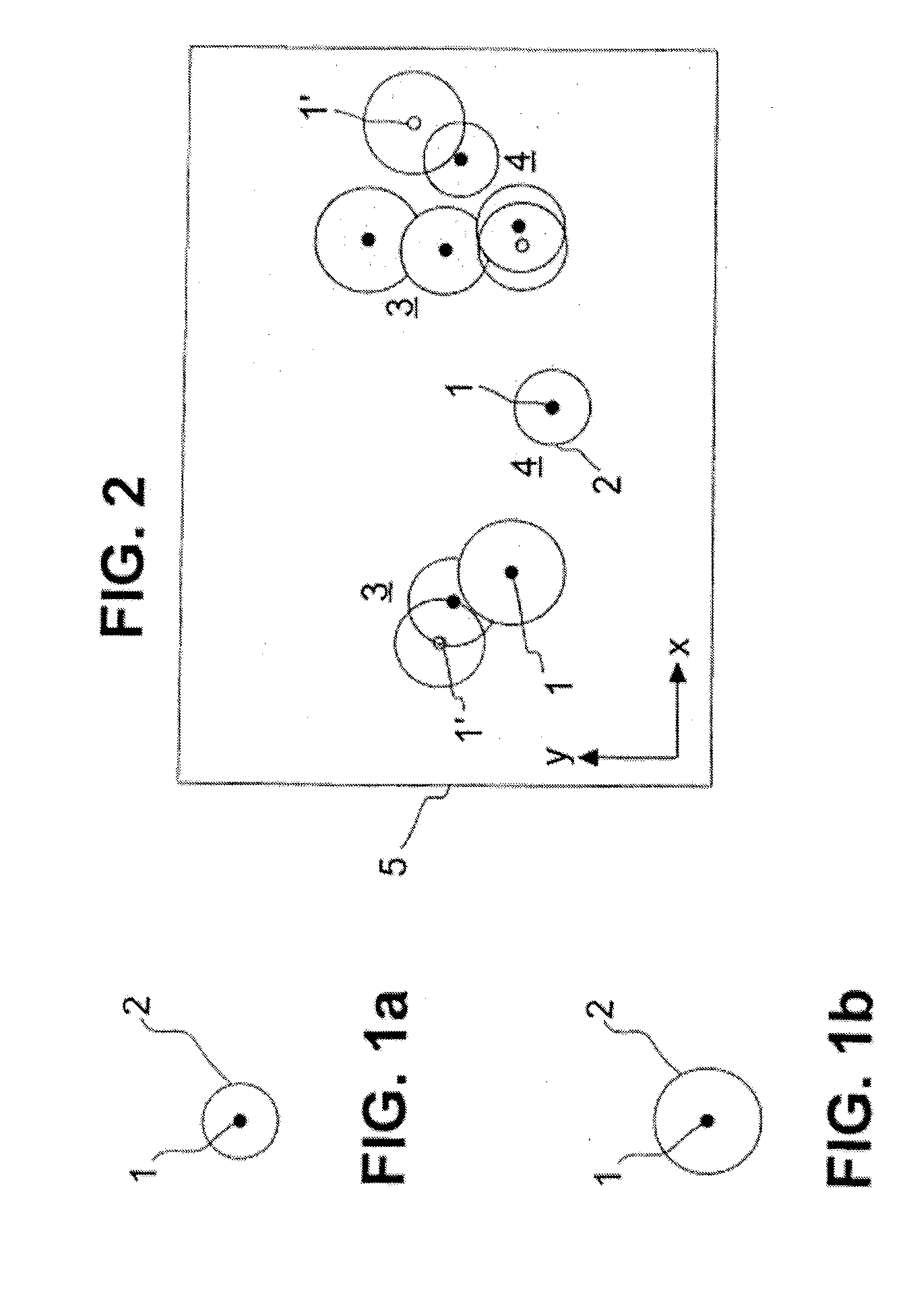
[0039]FIG. 1a schematically illustrates a marker molecule 1 which has been excited to fluorescence. The fluorescing marker molecule 1 can only be detected with a limited optical resolution in a microscope, due to physical laws. Even if the microscope reaches the diffraction limit of the optical resolution, the photons of the fluorescing marker molecule 1 are still scattered due to diffraction, and the marker molecule 1 is detected as a diffraction spot 2. The microscope therefore must reproduce a larger object, as the image, than the geometric expansion of the marker molecule 1 as indicated in FIG. 1 schematically as a black circle. This is shown in FIG. 1 by the diffraction spot 2. The size of the diffraction spot 2 depends on the quality of the microscope device used, and is defined by the ha...


PUM


Abstract

A method for high-resolution 3D localization microscopy, in which sample is used which has a boundary surface on the imaging side. The sample is illuminated with excitation light in order to excite fluorescence markers to emit light. The sample is imaged to a still image along an imaging direction, by means of imaging optics. The still image contains images of the fluorescing fluorescence markers. The imaging optics has a focal plane and an optical resolution. The excitation and imaging steps are repeated multiple times so that multiple still images are obtained. The excitation steps create images of at least a subset of the fluorescing fluorescence markers isolated in each of the still images. A location is determined in each of the still images and this location has a precision which is greater than the optical resolution. A high-resolution composite image is generated from the locations determined in this manner.

Description

RELATED APPLICATIONS[0001]The present application claims priority benefit of German Application No. DE 10 2013 208 927.9 filed on May 14, 2013, the contents of which is incorporated by reference in its entirety.FIELD OF THE INVENTION[0002]The invention relates to a method for high-resolution 3D localization microscopy, wherein a sample is used which has a boundary surface on the imaging side thereof, the sample is illuminated with excitation light in an excitation step in order to excite fluorescence markers in the sample to fluoresce, in an imaging step the sample is imaged to a still image along an imaging direction by means of an imaging optics, wherein the still image contains images of the fluorescing fluorescence markers and the imaging optics has a focal plane and an optical resolution, and the excitation step and the imaging step are repeated multiple times such that multiple still images are produced in this way, wherein the excitation steps are carried out in such a manner...

Claims


Application Information

Patent Timeline
IPC IPC(8): G01N21/64
CPCG01N21/6458G01N21/6428G02B21/0076G02B21/16G02B21/361G02B21/367G02B27/58
Inventor RITTER, JOERGSIEBENMORGEN, JOERGKALKBRENNER, THOMAS
Owner CARL ZEISS MICROSCOPY GMBH
Why Eureka
Try Eureka