
System and Method for a Switchable Capacitance

a capacitance and switchable technology, applied in the field of electronic devices, can solve the problems of degrading the quality factor (q) of the signal, and achieve the effect of reducing the degrading quality factor

Active Publication Date: 2014-11-20
INFINEON TECH AG
View PDF2 Cites 13 Cited by
  • Summary
  • Abstract
  • Description
  • Claims
  • Application Information

AI Technical Summary

Benefits of technology

The patent text describes a circuit that allows for the control of capacitance in a way that ensures the resistance and capacitance of different cells in the circuit are within acceptable tolerances. This can improve the overall performance and reliability of the circuit.

Problems solved by technology

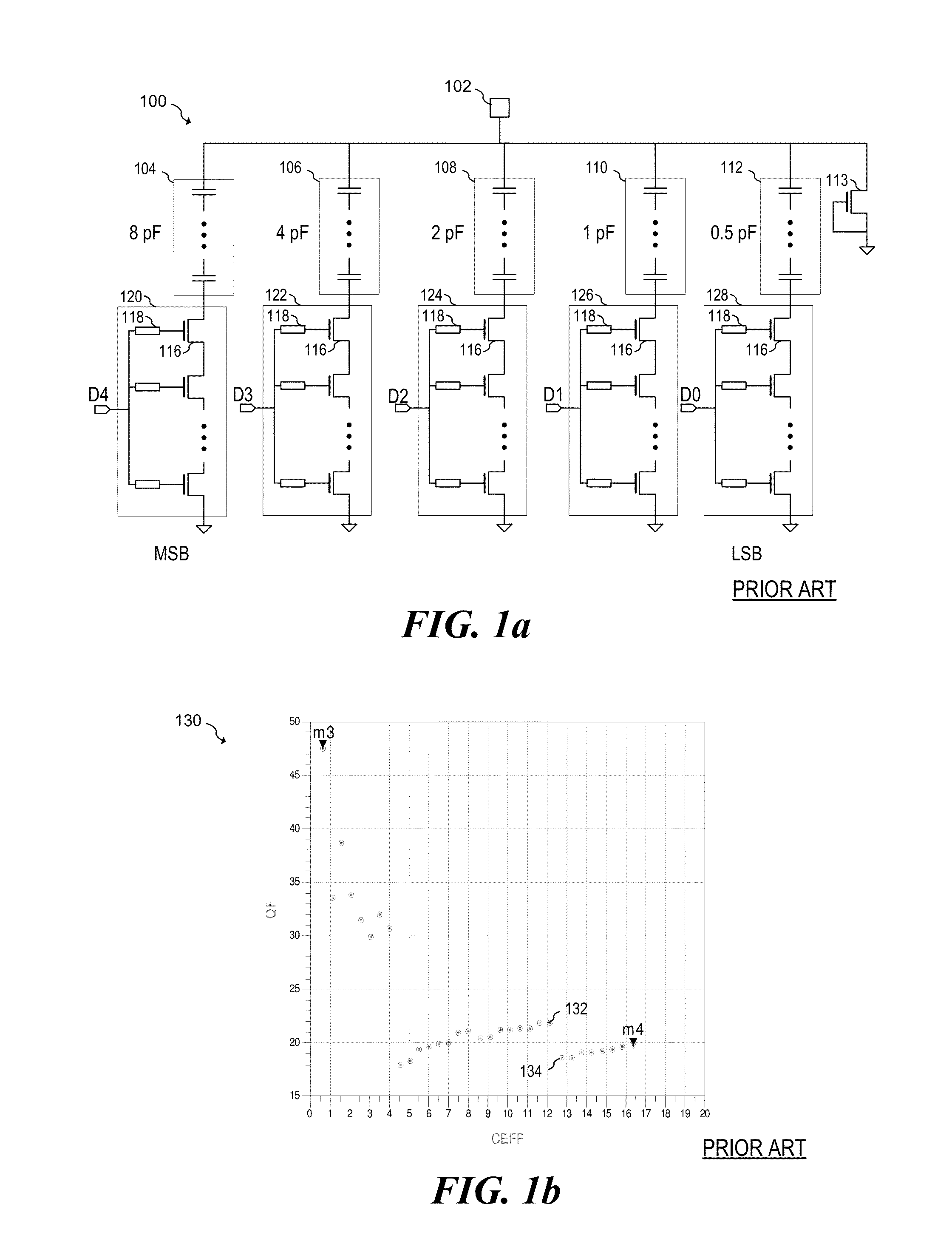
One challenge in the design of a switchable capacitor is maintaining a high quality factor (Q), which may be degraded by the resistance of the controllable switches.

Method used


Image

  • System and Method for a Switchable Capacitance
  • System and Method for a Switchable Capacitance
  • System and Method for a Switchable Capacitance

Examples


Embodiment Construction

[0015]The making and using of the presently preferred embodiments are discussed in detail below. It should be appreciated, however, that the present invention provides many applicable inventive concepts that can be embodied in a wide variety of specific contexts. The specific embodiments discussed are merely illustrative of specific ways to make and use the invention, and do not limit the scope of the invention.

[0016]The present invention will be described with respect to preferred embodiments in a specific context, a system and method for a switchable capacitance that may be used in RF circuits to provide tuning for antennas, matching networks and filters. The invention may also be applied to other systems and applications including other circuits that utilize a programmable capacitance such as digitally tunable oscillators to enable a wide output frequency range and charge-pumps to enable variable frequency operation.

[0017]FIG. 1a illustrates a conventional digitally tunable capac...


PUM


Abstract

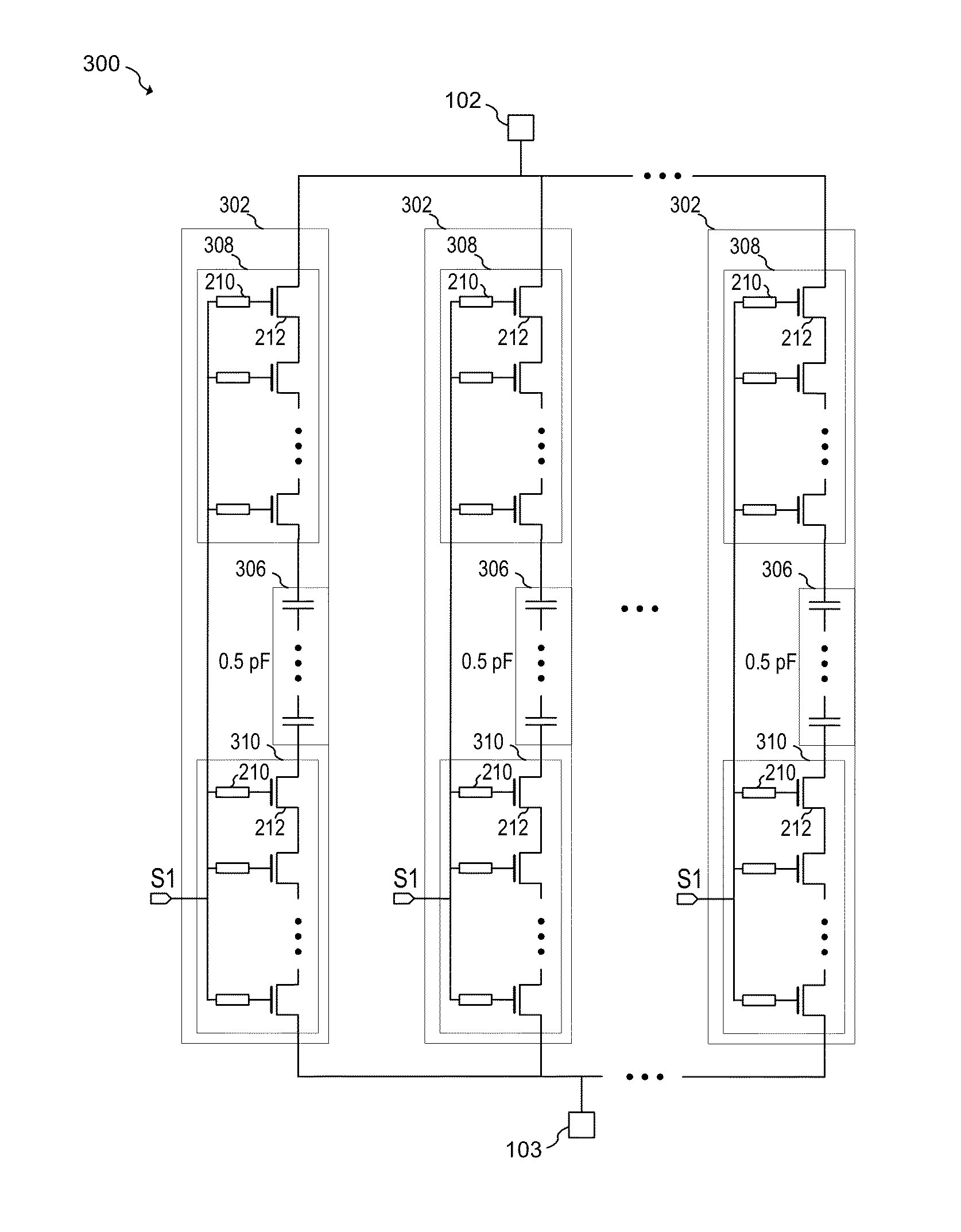
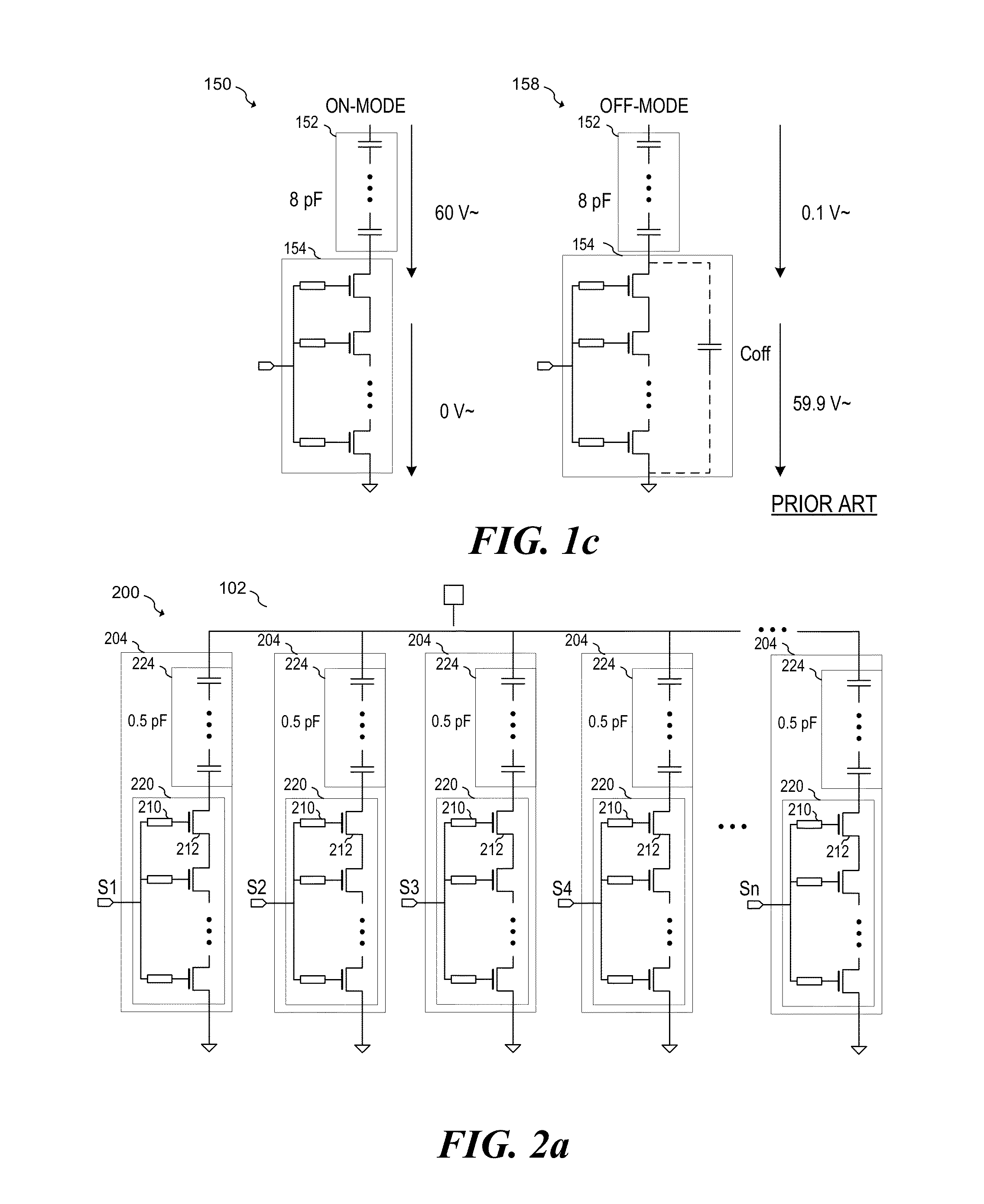
In accordance with an embodiment, a switchable capacitance circuit includes a plurality of capacitance-switch cells that each has a first semiconductor switching circuit and a capacitance circuit having a first terminal coupled to the first semiconductor switching circuit. A resistance of the first semiconductor switching circuit of a first switch-capacitance cell of the plurality of capacitance-switch cells is within a first tolerance of a resistance of the first semiconductor switching circuit of a second capacitance-switch cell of the plurality of capacitance-switch cells, and a capacitance of the capacitance circuit of the first capacitance-switch cell is within a second tolerance of a capacitance of the capacitance circuit of the second capacitance-switch cell.

Description

TECHNICAL FIELD[0001]The present disclosure relates generally to an electronic device, and more particularly to a system and method for a switchable capacitance.BACKGROUND[0002]Tunable passive elements, such as capacitors and inductors, are used in a variety of radio frequency (RF) circuits to implement adjustable matching networks for antennas and power amplifiers, and to provide adjusting tuning for high frequency filters. Due to the high demand and production of portable devices, such tunable passive elements may be found in products such as cellular telephones, smart phones and portable computers. Providing tuning to RF circuits in such products allows these products to provide high performance RF transmission and reception in a variety of RF conditions. Programmable tuning is also helpful in RF devices that are configured to operate over different RF bands and / or configured to operate using different standards.[0003]Tunable capacitors may be implemented in a number of ways. For...

Claims


Application Information

Patent Timeline
Patent Type & Authority Applications(United States)
IPC IPC(8): H03J5/24
CPCH03J5/244H03J2200/10
Inventor BAKALSKI, WINFRIED
Owner INFINEON TECH AG
Learn More