Mutual capacitive touch control device

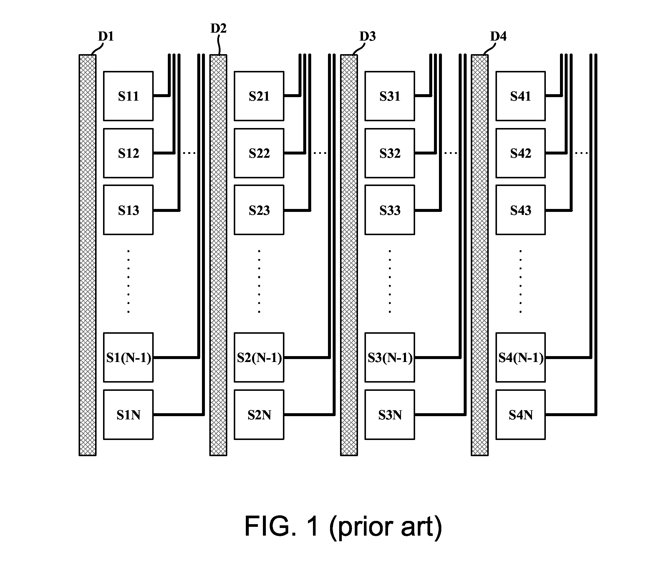
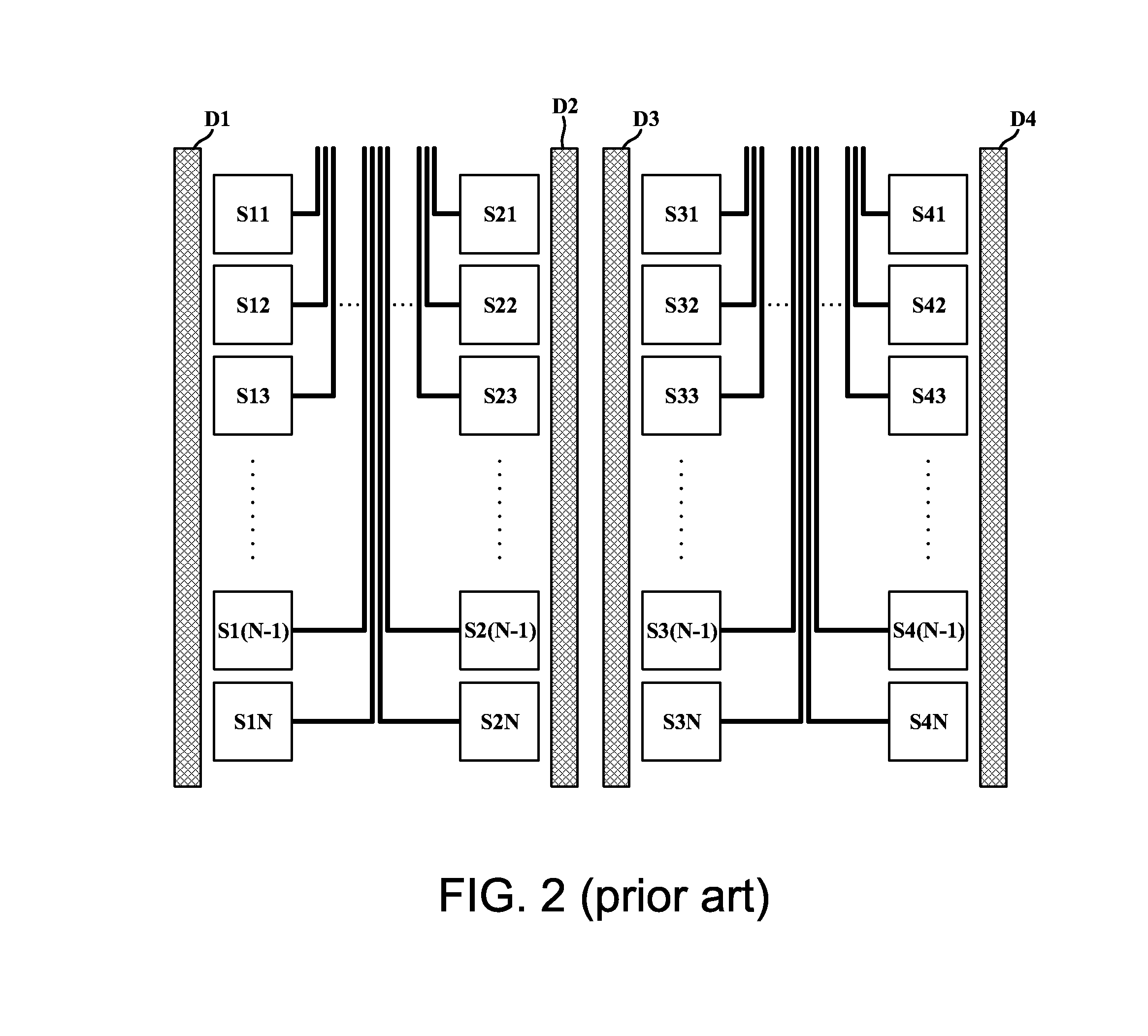
a capacitive touch control and capacitive technology, applied in the direction of instruments, computing, electric digital data processing, etc., can solve the problems of poor linearity of the electrode arrangement in fig. 2, misjudge coordinates, uneven distribution of unit sensing regions formed by driving electrodes and sensing electrodes, etc., to prevent the problem of impedance mismatch of sensing electrodes and poor linearity

Inactive Publication Date: 2014-11-20
TYCO HEALTHCARE GRP LP +1
View PDF3 Cites 13 Cited by
  • Summary
  • Abstract
  • Description
  • Claims
  • Application Information

AI Technical Summary

Benefits of technology

[0009]The invention is directed to an electrode pattern for a mutual capacitive touch control device. By adopting an electrode arrangement different from the prior art, the mutual capacitive touch control device according to the present invention is capable of preventing the issues of impedance mismatch of sensing electrodes and poor linearity. Further, by adding a shielding portion to driving electrodes, the mutual capacitive touch control device according to the present invention also lowers the possibility of a subsequent circuit misjudging coordinates of a touch point.

Problems solved by technology

This occurrence may lead a subsequent circuit to misjudge coordinates of a touch point.
However, the electrode arrangement in FIG. 2 suffers from poor linearity.
More specifically, distances between the driving electrodes are not equal, and unit sensing regions formed by the driving electrodes and the sensing electrodes are also unevenly distributed.

Method used


Image

  • Mutual capacitive touch control device
  • Mutual capacitive touch control device
  • Mutual capacitive touch control device

Examples


Embodiment Construction

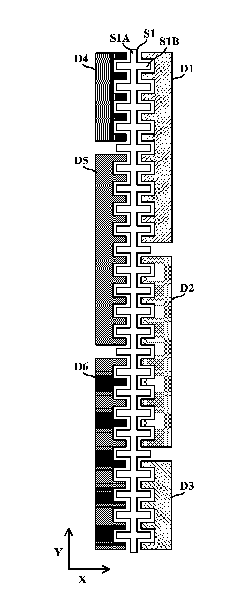
[0022]A single-layer mutual capacitive touch control system is provided according to an embodiment of the present invention. FIG. 3(A) shows a partial electrode arrangement of the single-layer mutual capacitive touch control system, which can be regarded as an electrode combination. The electrode denoted S1 is a sensing electrode, and electrodes denoted D1 to D6 are independent driving electrodes. As shown in FIG. 3(A), a main stem S1A of a sensing electrode S1 has a substantially strip-shaped planar contour and has a longer side substantially parallel to the Y direction. The sensing electrode S1 further includes a plurality of electrode fingers, e.g., electrode fingers S1B. The electrode fingers having substantially rectangular planar contours extend from the main stem S1A toward the X direction or toward opposite the X direction. As shown in FIG. 3(A), each of the main bodies of the driving electrodes D1 to D6 has a plurality of recesses, which correspond to and interleave with th...


PUM


Abstract

A mutual capacitive touch control device includes a sensing electrode, a first driving electrode and a second driving electrode. The sensing electrode includes a main stem, a plurality of electrode fingers and a plurality of second electrode fingers. The main stem has strip-shaped planar contour and a longer side parallel to a first direction. The first electrode fingers extend from the main stem toward a second direction perpendicular to the first direction. The second electrode fingers extend from the main stem toward opposite the second direction. The first driving electrode includes a first main body. The first main body has a plurality of first recesses corresponding to and interleaved with the first electrode fingers. The second driving electrode includes a second main body. The second main body has a plurality of second recesses corresponding to and interleaved with the second electrode fingers.

Description

[0001]This application claims the benefit of Taiwan application Serial No. 102117243, filed May 15, 2013, the subject matter of which is incorporated herein by reference.BACKGROUND OF THE INVENTION[0002]1. Field of the Invention[0003]The invention relates in general to a touch control system, and more particularly, to a design of an electrode pattern in a touch control system.[0004]2. Description of the Related Art[0005]Operating interfaces of recent electronic products have become increasingly user-friendly and intuitive with the progressing technology. For example, through a touch screen, a user can directly interact with applications as well as input messages / texts / patterns with fingers or a stylus, thus eliminating complexities associated with other input devices such as a keyboard or buttons. In practice, a touch screen usually comprises a touch panel and a display provided at the back of the touch panel. According to a touch position on the touch panel and a currently displaye...

Claims


Application Information

Patent Timeline
Patent Type & Authority Applications(United States)
IPC IPC(8): G06F3/041G06F3/044
CPCG06F3/044G06F3/0418G06F3/0443G06F3/0448G06F2203/04107
Inventor LIU, TZU-WEI
Owner TYCO HEALTHCARE GRP LP
Why Eureka
Try Eureka