

Wide angle lens and imaging apparatus
- Summary
- Abstract
- Description
- Claims
- Application Information
AI Technical Summary
Benefits of technology
Problems solved by technology
Method used
Image

Examples
first embodiment
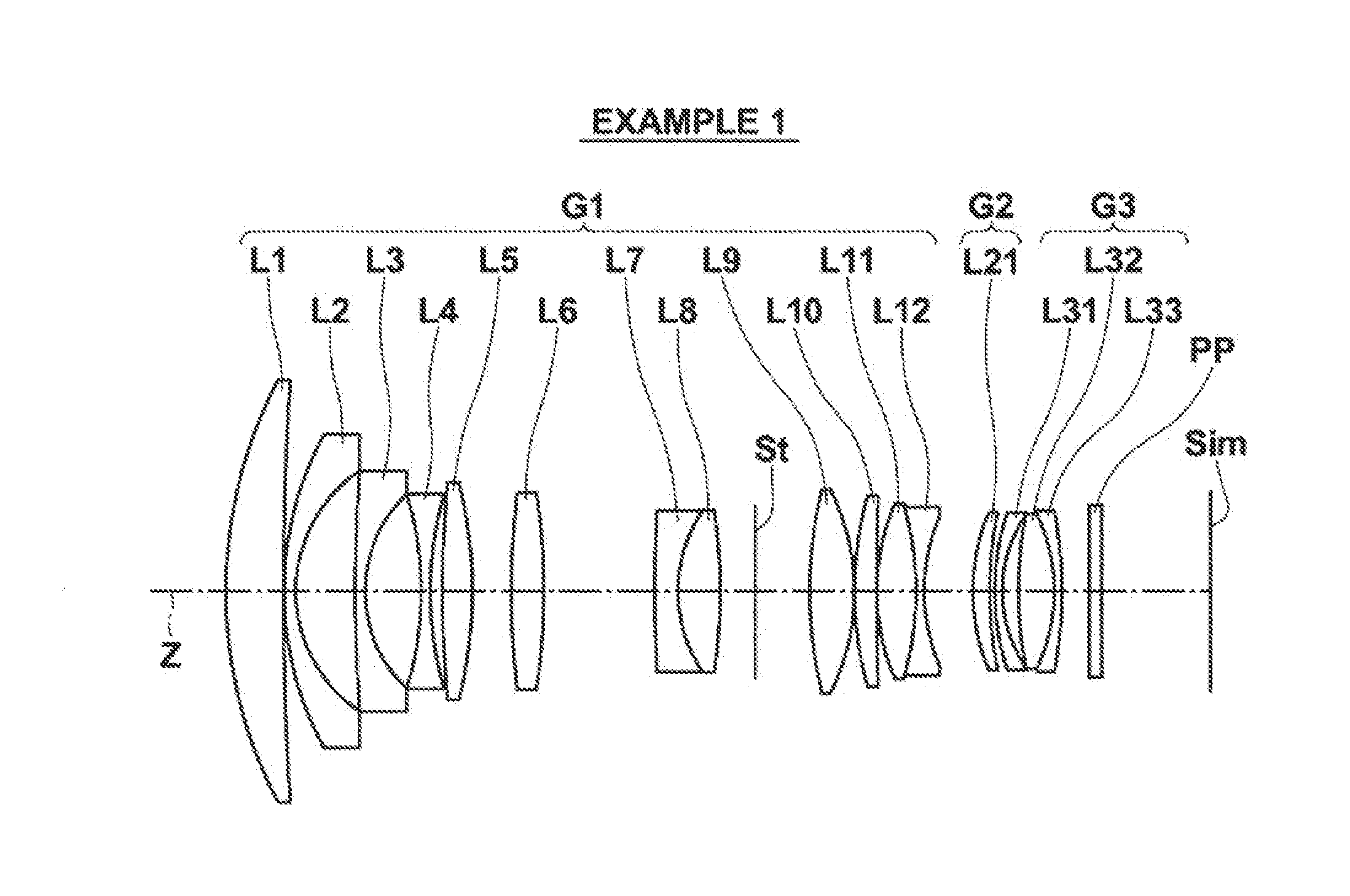
[0051]The wide angle lens of the first embodiment substantially consists of: a first lens group G1 having a positive refractive power, a second lens group G2 that moves during focusing operations, and a third lens group G3, provided in this order from the object side. The first lens group G1 and the third lens group G3 are fixed in the direction of the optical, axis during focusing operations, and focusing is performed by moving the second lens group G2 along the optical axis Z.
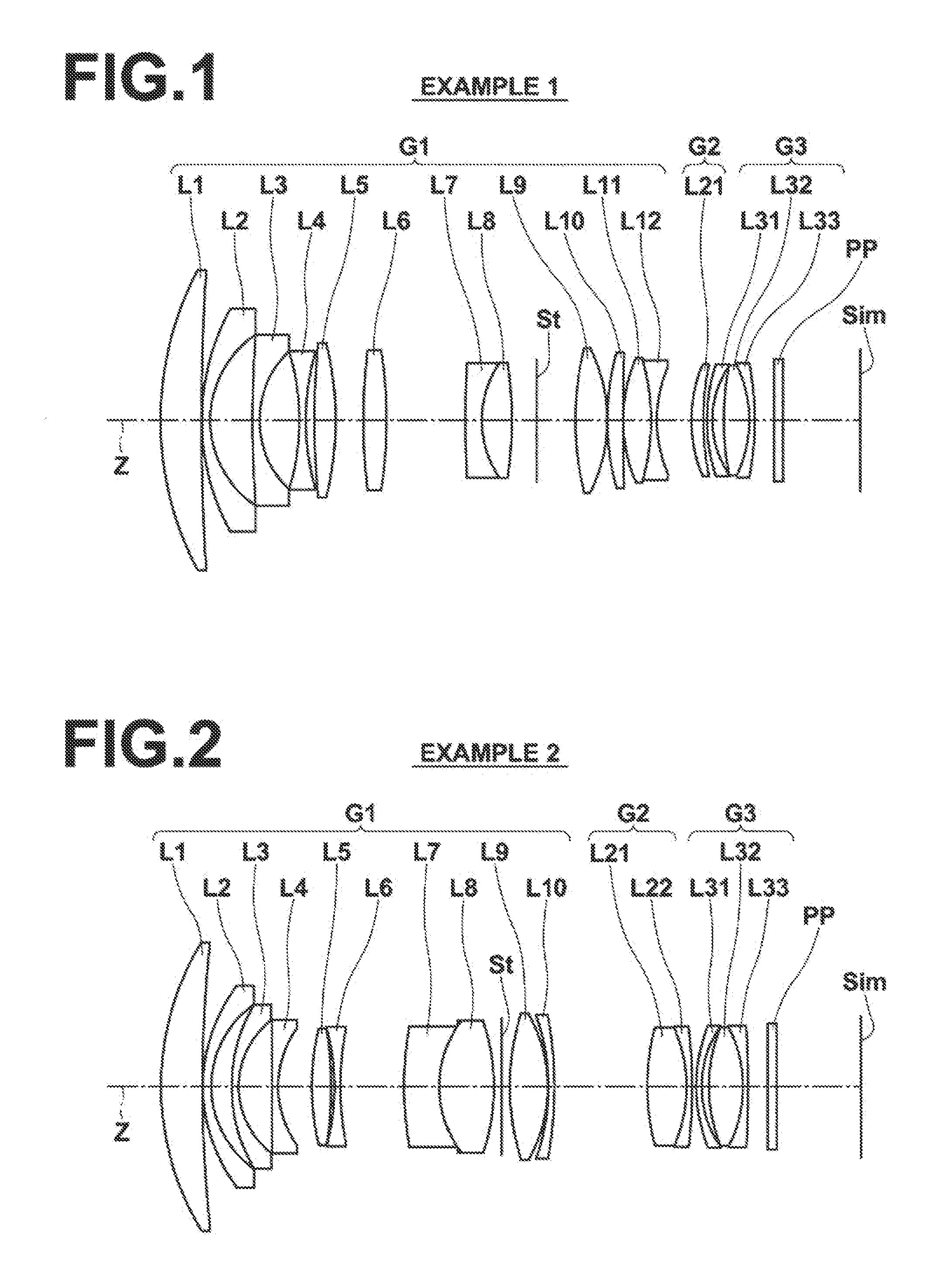
[0052]The lens configuration illustrated in FIG. 1 shows the arrangement of lenses when focused on an object at an infinite distance (a state focused on infinity) . In FIG. 1, the left side is the object side, and the right side is the image side.
[0053]In the example illustrated in FIG. 1, an aperture stop St is provided within the first lens group G1. Note that the aperture stop St illustrated in FIG. 1 does not necessarily represent the size or shape thereof, but only the position thereof along the optical ...
second embodiment
[0089]In the case that Conditional Formula (3) is satisfied, variations in chromatic aberrations during focusing operations can be favorably suppressed. In order to cause the advantageous effects obtained by satisfying Conditional Formula (3) to become more prominent, it is more preferable for Conditional Formula (3-1) to be satisfied, and even more preferable for Conditional Formula (3-2) to be satisfied. In the second embodiment, the value of ν2p is set to be greater than 80, which is sufficiently large. Therefore, Conditional Formula (3-2) is satisfied, and variations in chromatic aberrations during focusing operations can be favorably suppressed.
[0090]In the second embodiment, the basic lens configurations of the third lens group G3 are the same as those of the first embodiment. Thereby, the same advantageous effects as those obtained by the configurations in common with those of the first embodiment can be obtained.
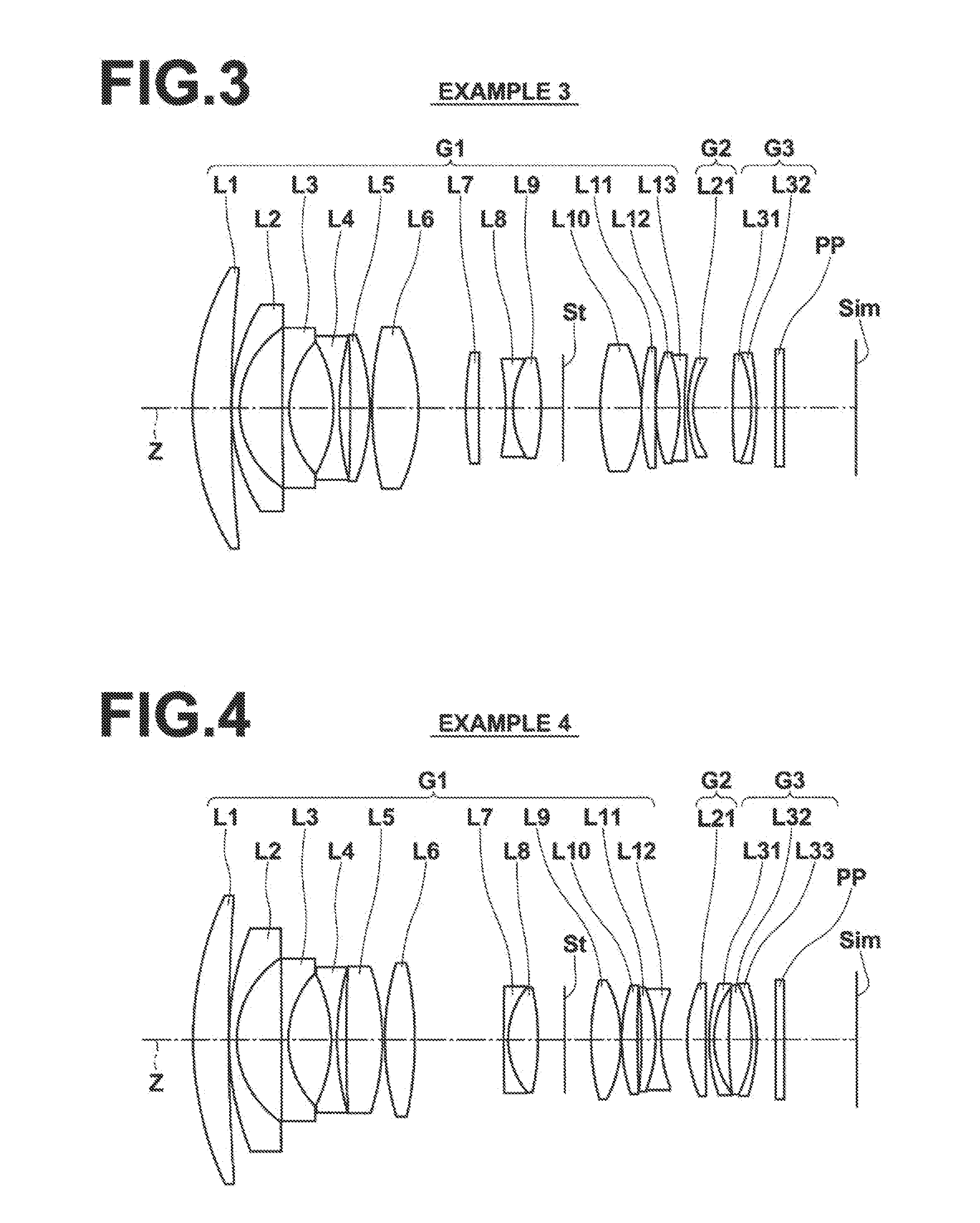
[0091]Next, a wide angle lens according to a third, embodiment ...
third embodiment
[0096]Further, the configurations of the lenses within the first lens group G1 more toward the image side than the aperture stop St may be a biconvex tenth lens L10, a biconvex eleventh, lens L11, and a cemented lens formed by cementing a biconvex twelfth lens L12 and a biconcave thirteenth lens L13 together, provided in this order from the object side. In the third embodiment, the tenth lens L10, the eleventh lens 11, and the twelfth lens L12 bear the main portion of the positive refractive power of the entire system. By providing these lenses toward the image side of the aperture stop St, the incident angle of rays of light which have passed through the peripheral portions of the first lens group G1 (portions having high image heights) and enter the second lens group G2 can be maintained small. Therefore, variations in the angle of view during focusing operations can be suppressed. In addition, by configuring a thirteenth lens L13 to be of a biconcave shape, spherical aberration a...
PUM
 Abstract
Description
Claims
Application Information