Centrifugal refrigerant vapour compressors

Inactive Publication Date: 2014-11-20
VENUS SYST
View PDF19 Cites 40 Cited by
  • Summary
  • Abstract
  • Description
  • Claims
  • Application Information

AI Technical Summary

Benefits of technology

[0013]The present invention is generally concerned with providing an improved centrifugal refr...

Problems solved by technology

Typical hot water temperature from a commercial/industrial boiler is 82° C. Conventional refrigeration systems, on the other hand, including those using the types of oil-free centrifugal compressor...

Method used


Image

  • Centrifugal refrigerant vapour compressors
  • Centrifugal refrigerant vapour compressors
  • Centrifugal refrigerant vapour compressors

Examples


Embodiment Construction

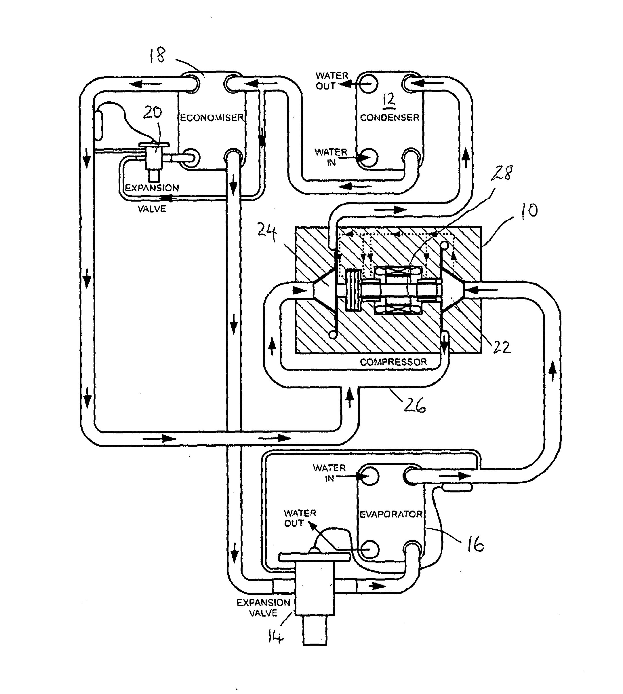
[0104]FIG. 3 shows a refrigeration circuit in accordance with an embodiment of the present invention that might be used, for example, to generate chilled water for a building air conditioning system. In a preferred form, the operating parameters of the system might be designed to provide sufficient heat output to heat a supply of low pressure hot water for the building, in addition to the chilled water for the air conditioning system.

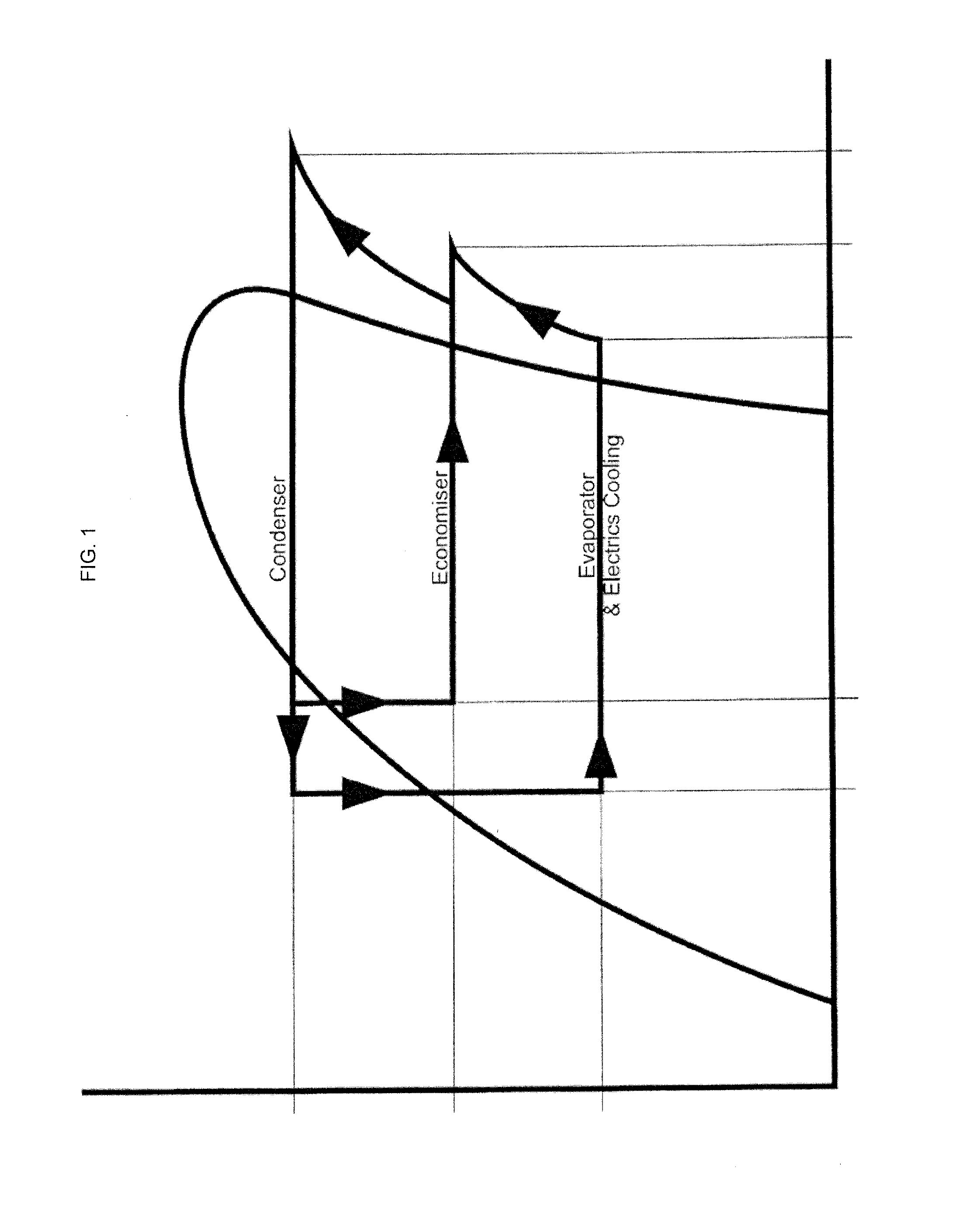
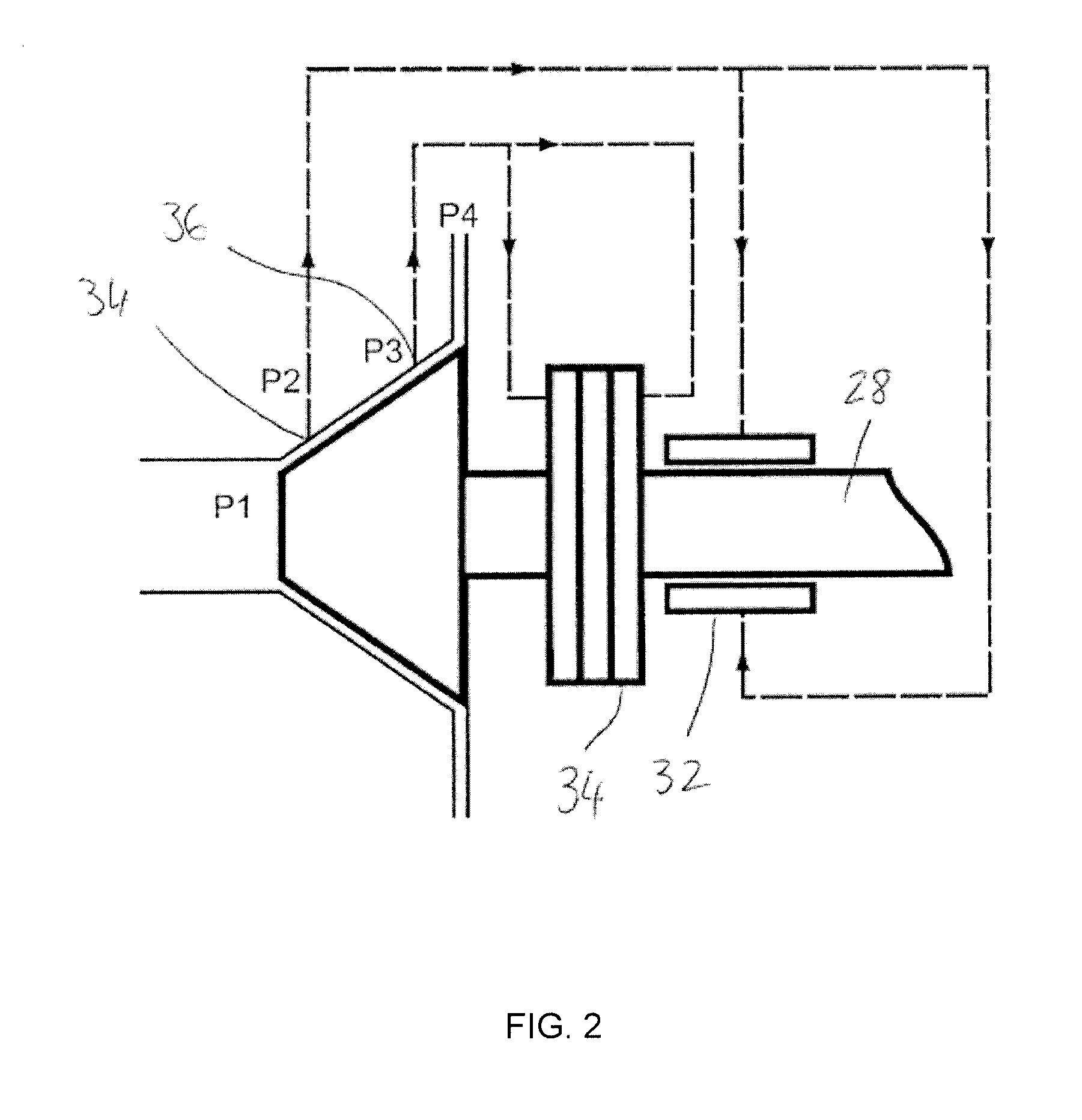
[0105]A refrigerant fluid circulates around the refrigeration system, which operates on a vapour-compression refrigeration cycle (see FIG. 1). The refrigerant enters a two-stage centrifugal compressor 10 in a superheated vapour state and is compressed, in two steps (lower pressure stage 1 and higher pressure stage 2) to a higher pressure and temperature. Superheated refrigerant vapour from the second stage compressor discharge outlet passes to a condenser 12, where it is cooled, the superheat and latent heat of condensation is removed and the vapour con...


PUM


Abstract

A refrigerant compressor (10) for use in a chiller-heater system that can provide chilled water at less than 10° C. and hot water at more than 80° C. without the need for additional heat input, the compressor (10) being configured to provide a compression ratio of at least 18:1 and a temperature lift across the compressor of at least 80K, and the refrigerant fluid being selected to give the desired temperature lift without the pressure at the compressor outlet exceeding 25 bar.

Description

FIELD OF THE INVENTION[0001]This invention relates to centrifugal vapour compressors, in particular, although not necessarily exclusively, electrically driven (e.g. electric motor driven) centrifugal vapour compressors. compressors in accordance with embodiments of the present invention are particularly suitable for use in refrigeration circuits and systems, such as those in air conditioning, direct expansion (DX) chilled water and other cooling systems, as well as for refrigerators (e.g. commercial refrigerators) and industrial process cooling.BACKGROUND[0002]Chilled water and DX systems are commonly used for air conditioning in commercial buildings. They are also used for process cooling and other numerous applications. They generally include at least one refrigeration circuit to provide chilled water or air that is then used in heat exchangers to cool air recirculating within terminal units or the air conditioning duct work within buildings.[0003]A typical refrigeration circuit f...

Claims


Application Information

Patent Timeline
IPC IPC(8): F04D29/057F25B1/00F04D27/00F04C18/02F04D17/12F25B29/00F25B49/02
CPCF04D29/057F25B29/003F25B1/00F04D27/007F04C18/02F04C18/0207F04D17/12F25B49/022F25B1/053F25B31/002F25B2400/01F25B2500/26F25B2700/171F16C33/1005F16C2362/52F16C2210/00F04D29/063F24F11/30F24F11/62F24F11/63F24F11/46F04D17/122F24F11/84F24F11/58F24F11/871F24F11/86F24F11/38F04D29/056F04D25/06F04D27/001F04D29/5806F25B1/10G05D23/1917F04D29/051F04D29/053F04D29/284F04D29/462F25B43/003F25B2400/23G05B13/024G05B2219/2614
Inventor CREAMER, MICHAEL
Owner VENUS SYST
Why Eureka
Try Eureka