
Positioning jig and improved methods to design and manufacture dental implants

a technology of dental implants and jigs, which is applied in the field of positioning jigs, can solve the problems of high mechanical complications of hybrid prostheses, inability to design and manufacture dental implants with individualized metal supports, and attachment to underlying teeth

Inactive Publication Date: 2014-11-20
LERNER TODD H
View PDF5 Cites 10 Cited by
  • Summary
  • Abstract
  • Description
  • Claims
  • Application Information

AI Technical Summary

Benefits of technology

The invention provides a positioning jig for preparing two or more adjacent teeth for a dental prosthesis, which has three or more parallel bores and means for attaching the member to a dental articulator. The invention also provides a method for preparing an artificial prosthesis with two or more adjacent teeth by using the positioning jig to align the teeth, drill the holes, and form rods and a dental mockup. This can save time and provide greater accuracy in preparing the prosthesis. Additionally, the invention provides a kit comprising a positioning jig and matching rigid struts for easy use in dental procedures.

Problems solved by technology

These hybrid prostheses have a high rate of mechanical complications.
Other mechanical complications include: the fracture of the resin support; fracture of attachment to underlying metal framework; or the fracture of the metal framework / implant bar.
They were not designed with individualized metal supports for denture teeth.
Furthermore, the teeth were added in sections with silicone matrices which are difficult to work with.
In particular, it is difficult to get the denture teeth to maintain their position in the silicone matrices.
Like the classical hybrid framework above, the vertical support component to the framework was insufficient.
Another issue with this technique is that some of the teeth may change position in the flask once the wax is eliminated.
Another complication with making improved hybrid frameworks is that each tooth must be individually drilled and individually fitted onto a post supporting the tooth in the denture material.
This requires great precision and is extremely time consuming

Method used


Image

  • Positioning jig and improved methods to design and manufacture dental implants
  • Positioning jig and improved methods to design and manufacture dental implants
  • Positioning jig and improved methods to design and manufacture dental implants

Examples


Embodiment Construction

[0035]5.1. Positioning Jigs

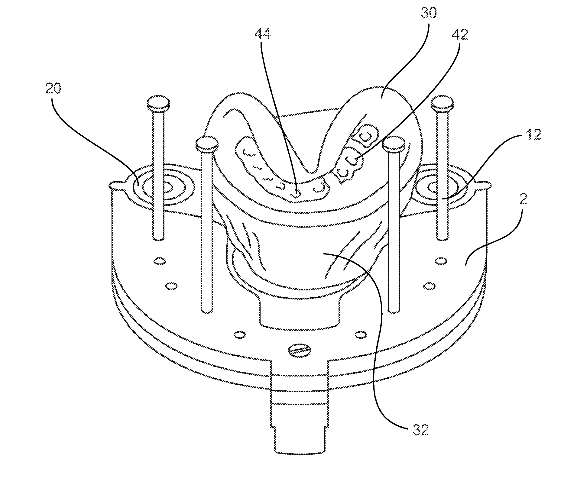
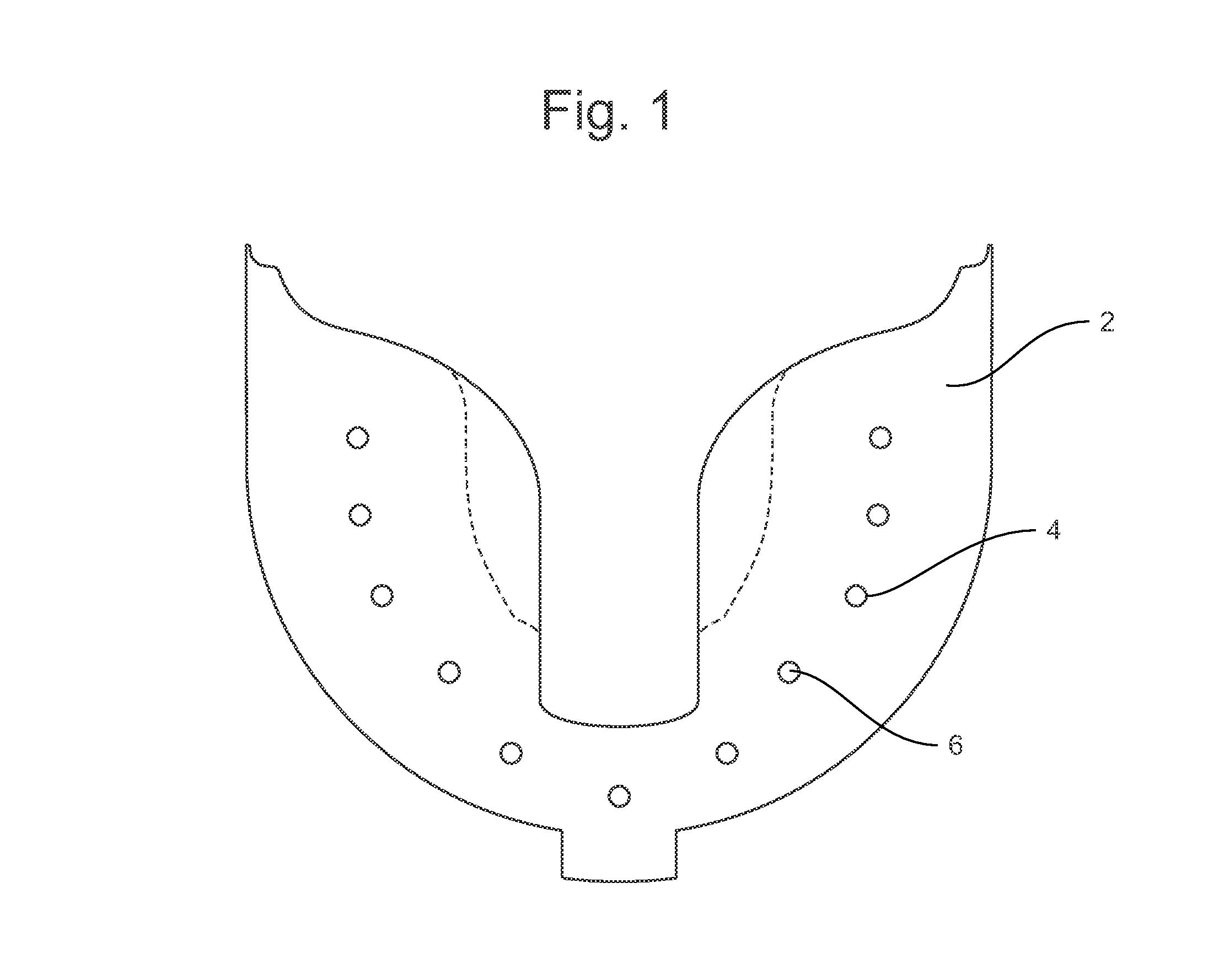
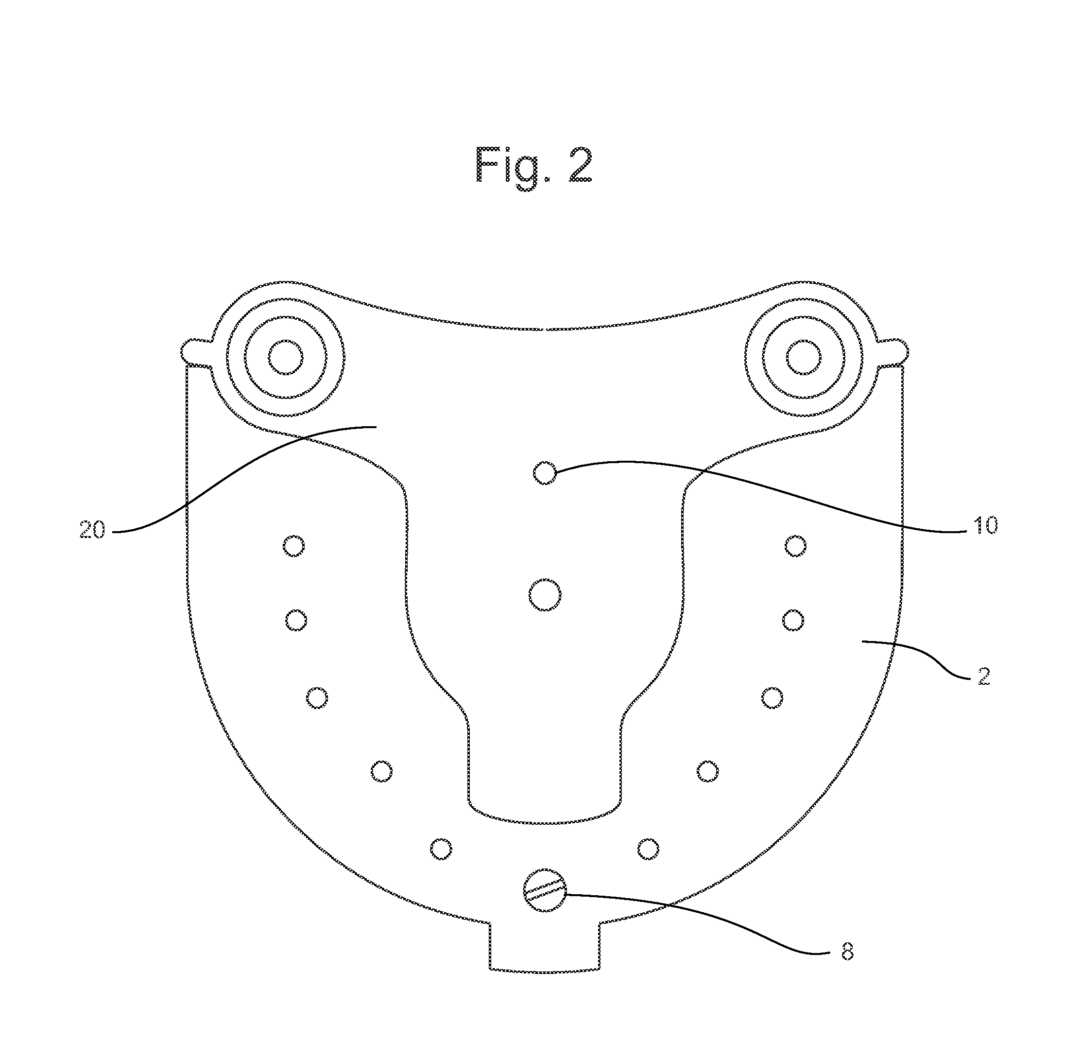
[0036]The invention provides a positioning jig for preparing two or more adjacent teeth for a dental prosthesis comprising: a member with (i) three or more parallel bores in the member; and (ii) one or more means for attaching the member to a dental articulator. In one embodiment, the member has four or more parallel bores. In another embodiment, the member has six or more parallel bores. In a preferred embodiment, the parallel bores are perpendicular to the plane of the member. In one non-limiting embodiment of the positioning jig, at least three of the parallel bores are of a first diameter and at least three of the parallel bores are of a second diameter. In a non- limiting preferred embodiment, the parallel bores in the member are distributed evenly on either side of the means for attaching to the dental articulator.

[0037]The positioning jig may have a means for attaching the member to the dental articulator which may be a screw; a pin and a screw; a p...


PUM

PropertyMeasurementUnit
sizeaaaaaaaaaa
diameteraaaaaaaaaa
compositionaaaaaaaaaa

Abstract

This invention is directed to a positioning jig for preparing a two or more of adjacent teeth for a dental prosthesis comprising a member with (i) three or more parallel bores in the member and (ii) one or more means to attach the member to a dental articulator. The invention is also directed to methods of use of the position jig such as to prepare a series of aligned holes in teeth or aligned holes mockup of a dental bridge for a prosthesis.

Description

CROSS REFERENCE TO RELATED APPLICATIONS[0001]This application claims the benefit of U.S. Provisional Appn. No. 61 / 565,649 filed Dec. 1, 2011, Lerner, having Atty. Docket No. LER11001USV, which is hereby incorporated by reference in its entirety.1. FIELD OF THE INVENTION[0002]This invention relates a positioning jig for aligning the holes in artificial denture teeth in an artificial tooth arrangement (ATA) for replacing a plurality of teeth. The invention also relates to methods of design and methods of manufacture of dental implants in general, particularly for making hybrid prostheses.2. BACKGROUND OF THE INVENTION[0003]2.1. Introduction[0004]For patients who have lost many adjacent teeth, dental prostheses are widely used. These prostheses may be either removable full or partial dentures or fixed full or partial dentures. A common type of fixed denture is the “hybrid prosthesis” a term generally used to describe a wide variety of dental prostheses with materials of different compo...

Claims


Application Information

Patent Timeline
Patent Type & Authority Applications(United States)
IPC IPC(8): A61C11/08A61C13/00A61C13/34
CPCA61C11/087A61C13/00A61C13/34A61C13/083A61C13/087A61C11/001A61C11/003A61C11/08A61C1/084Y10T29/49567
Inventor LERNER, TODD H.
Owner LERNER TODD H
Learn More