Device for guiding piercing tools for placing a glenoid implant

a technology for guiding tools and glenoid implants, which is applied in the field of guiding tools for placing glenoid implants, can solve the problems of limiting the mobility of the shoulder, harming the stability of the final implant, and loss of articular congruence, so as to limit the risks of removing a complete shoulder prosthesis

Active Publication Date: 2014-11-20
FOURNITURES HOSPITALERES IND +2
View PDF8 Cites 4 Cited by
  • Summary
  • Abstract
  • Description
  • Claims
  • Application Information

AI Technical Summary

Benefits of technology

The patent describes a guide device that helps to position shoulder prosthesis components accurately. The guide device is adjustable to different patient anatomies and can be easily positioned using imaging techniques. It is designed to reduce the risk of removing a complete shoulder prosthesis in case of patient pathology. The guide device has a bearing surface with a convex spherical portion that matches the concave spherical surface of the glenoid cavity, which ensures correct positioning of the piercings of the fastening elements. This eliminates the need for osteotomy, reducing the risk of complications. Overall, the guide device improves the accuracy of shoulder replacement surgeries.

Problems solved by technology

The deterioration of the humeral head and the glenoid by primary or secondary osteoarthritis causes a loss of articular congruence, which is a source of pain and limits the mobility of the shoulder.
Such conflicts may harm the stability of the final implant and impose removal of the shoulder prosthesis.
Furthermore, protrusion of the fastening elements outside the bone would cause friction of the latter on the muscles or nerves (suprascapular), which may cause pain for the patient.
However, such a guide device may be unsuitable for implanting glenoid implants in patients with a particular anatomy or significant deteriorations of the glenoid.

Method used


Image

  • Device for guiding piercing tools for placing a glenoid implant
  • Device for guiding piercing tools for placing a glenoid implant
  • Device for guiding piercing tools for placing a glenoid implant

Examples


second embodiment

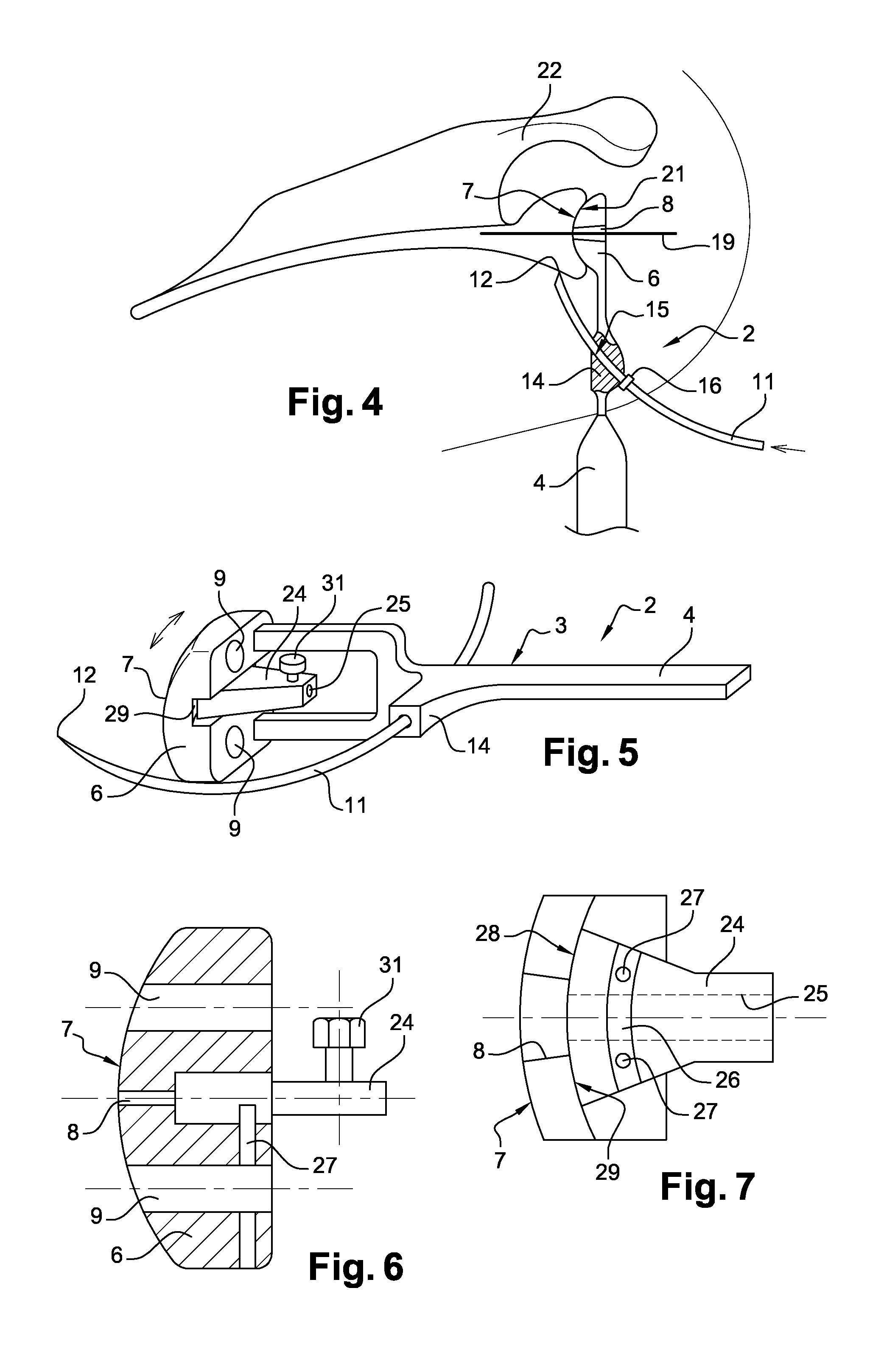
[0092]FIGS. 5 to 7 show a guide device 2 that differs from that shown in FIGS. 1 to 4 essentially in that it comprises a guide member 24 rotatably mounted with respect to the guide body 3, the guide member 24 including a passage channel 25 arranged to emerge across from the through orifice 8 and designed for passage of the support pin 19. Advantageously, the passage channel 25 has a passage cross-section that is smaller than the passage cross-section of the through orifice 8.

[0093]As shown more particularly in FIGS. 6 and 7, the guide member 24 comprises a groove 26 in the shape of an arc of circle with an axis passing through the center of the convex spherical surface portion, and the guide device 2 comprises two studs 27 mounted on the bearing portion 6 and extending parallel to the axis of the arc of circle-shaped groove 26, the studs 27 being arranged to cooperate with the arc of circle-shaped groove 26 so as to guide the rotation of the guide member 24 with respect to the bear...

third embodiment

[0096]FIG. 8 shows a guide device 2 that differs from that shown in FIGS. 1 to 4 essentially in that the reference member 5 is formed by a rectilinear pin.

fourth embodiment

[0097]FIG. 9 shows a guide device 2 that differs from that shown in FIG. 7 essentially in that the adjustment means include, in place of the stop ring 16, a thread 32 formed on the reference member 5 and arranged to cooperate with a tapping formed in the assembly orifice 15 provided on the mounting portion 14.


PUM


Abstract

A guide device having a guide body including a bearing surface designed to bear in a glenoidal cavity of a scapula that has been prepared beforehand, the guide body including at least one through orifice emerging in the bearing surface, a reference member mounted on the guide body and including a bearing portion designed to bear on the anterior cortex of the scapula, and adjustment means arranged to adjust the position of the reference member with respect to the guide body so as to adjust the distance between the bearing portion and an axis of the through orifice.

Description

TECHNICAL FIELD[0001]The present invention relates to a device for guiding piercing tools for placing a glenoid implant.BACKGROUND[0002]The deterioration of the humeral head and the glenoid by primary or secondary osteoarthritis causes a loss of articular congruence, which is a source of pain and limits the mobility of the shoulder.[0003]One solution to offset this joint deterioration consists of implementing a complete shoulder prosthesis including a humeral head designed to be engaged in the medullary channel of the humerus, and a glenoid implant designed to be implanted in the glenoidal cavity of the scapula. Such a complete shoulder prosthesis may be anatomical or said to be reversed when the convexity of the glenoid is transferred to the location of the humeral head.[0004]The fastening of the glenoid implant in a glenoidal cavity requires producing one or more bone drillings in the latter designed to house the fastening element(s) provided on the glenoid implant, such as a fin ...

Claims


Application Information

Patent Timeline
Patent Type & Authority Applications(United States)
IPC IPC(8): A61B17/17
CPCA61B17/1739A61B17/1778
Inventor VALENTI, PHILIPPEAARON, ALAIN
Owner FOURNITURES HOSPITALERES IND
Why Eureka
Try Eureka