
Trench cutting apparatus and method

Inactive Publication Date: 2014-11-27
IHC ENGINEERING BUSINESS LIMITED
View PDF18 Cites 2 Cited by
  • Summary
  • Abstract
  • Description
  • Claims
  • Application Information

AI Technical Summary

Benefits of technology

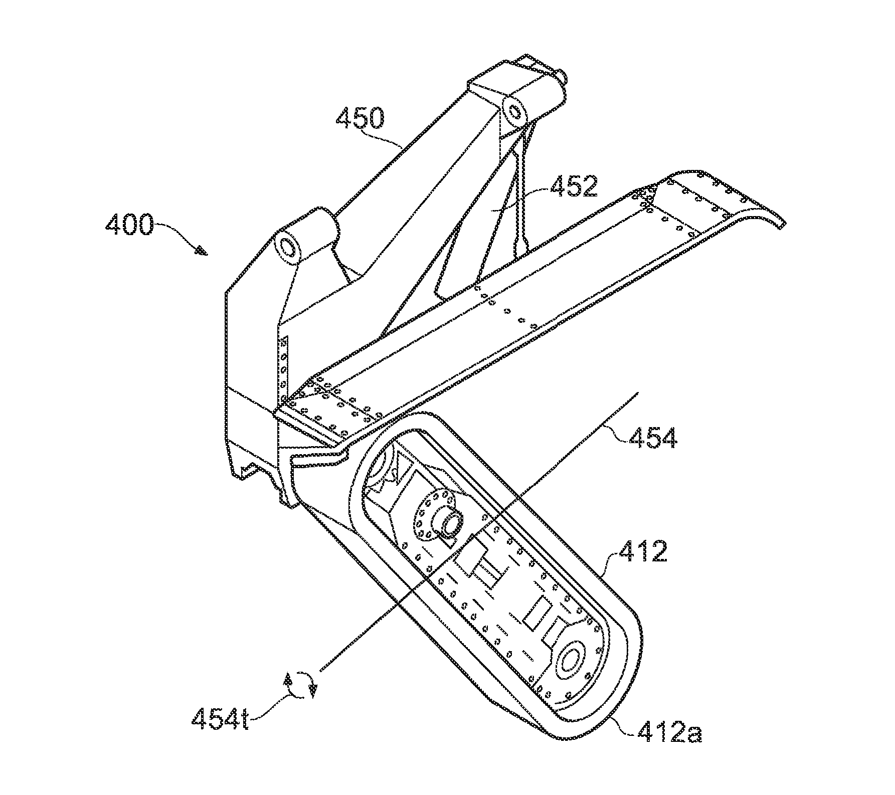
The present invention aims to solve the problem of undercutting the trench wall during a curved portion of a trench cut. The invention provides a trench cutting apparatus with an adjustable soil cutting device that can be adjusted to minimize undercutting of the trench wall. The method includes steps of adjusting the soil cutting device to an angle that minimizes the undercutting of the trench wall and then cutting the curved portion of the trench. This results in a more precise and accurate trench cut.

Problems solved by technology

An issue encountered by trench forming vehicles of this type is when the course of the trench executes a turn, in particular a turn of small turning radius.

Method used


Image

  • Trench cutting apparatus and method
  • Trench cutting apparatus and method
  • Trench cutting apparatus and method

Examples


Embodiment Construction

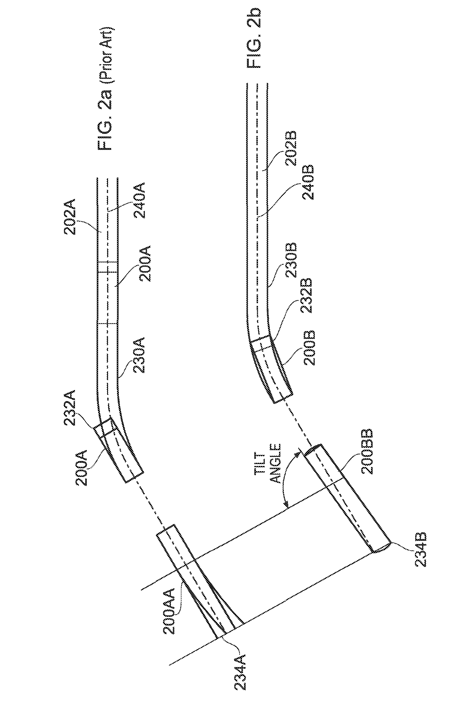
[0031]Referring now to the drawings, the present invention addresses the problem of the formation of undercuts in a trench side wall in curved portions of a trench when the trench is formed using apparatus of the prior art. Undercuts are formed with prior art apparatus in the outer trench wall, that is, the wall in a curved section of trench having a greater radius of curvature than an opposed inner trench wall.

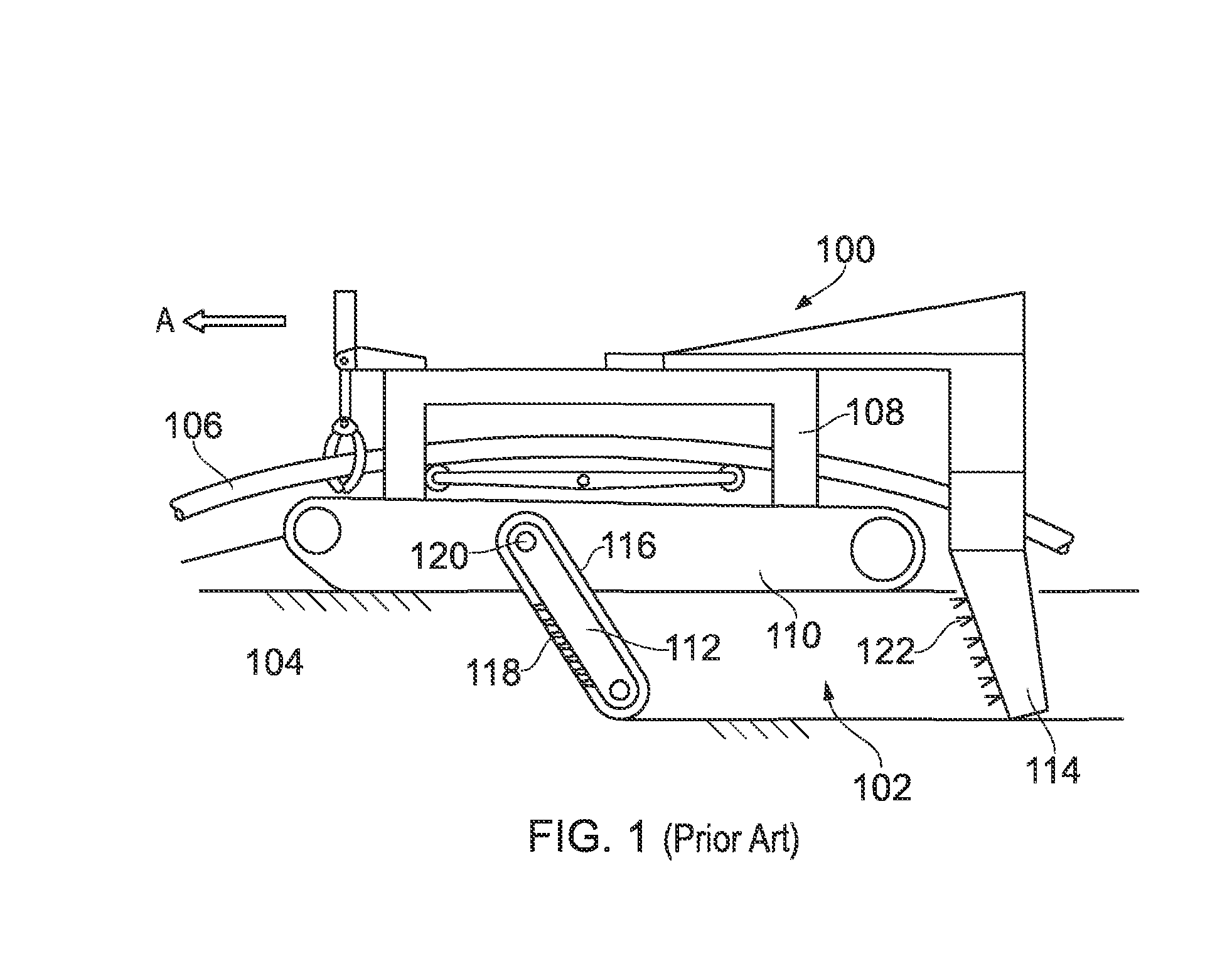
[0032]FIG. 1 shows on example of a prior art trenching apparatus 100, in this particular case configured for forming a trench 102 in the seabed 104 and simultaneously burying a pipeline 106 in the trench 102. For the avoidance of doubt, the apparatus according to the present invention may usefully be equipped with means both for trench forming and for simultaneous burying of a pipeline, but pipe burying means are not per se an essential feature of the apparatus of the invention. The prior art apparatus 100 includes a main body 108 and ground contacting conveying means 110 in ...


PUM


Abstract

A trench cutting apparatus comprises a main body portion, ground contacting conveying means on which the body portion is mounted and by which the apparatus can traverse the ground and at least one soil cutting device operable to cut a trench wherein the attitude of the soil cutting device is adjustable between a first use configuration configured for cutting a linear trench portion and a second use position configured for cutting a curved trench portion, said second use position being selected to minimise undercutting of a trench wall as said curved trench portion is formed.

Description

[0001]This invention relates to an apparatus and method for cutting a trench in the ground and more especially (but not exclusively) for cutting a trench in the bed of a body of water such as the bed of a lake or the sea bed. The invention relates in particular to apparatus and a method which avoids or reduces undercutting of the trench when executing a turn of the trench.BACKGROUND[0002]The formation of trenches in the ground is a well known requirement and is typically needed for burying utility supply means such as gas and water pipes and electricity and telecommunications cables. In underwater environments, the cutting of a trench is typically required for burial of pipes and cables and requires specially constructed or adapted equipment configured for underwater conditions, such as the nature of the seabed. Herein “seabed” is used to refer to the bed of the sea or of a lake or even a river, unless the context requires otherwise.[0003]Various apparatus for constructing a trench ...

Claims


Application Information

Patent Timeline
IPC IPC(8): E02F5/00E02F5/02E02F5/14E02F5/06
CPCE02F5/006E02F5/145E02F5/02E02F5/06E02F3/086E02F3/088E02F5/105
Inventor MANCHESTER, JONATHAN RALPH
Owner IHC ENGINEERING BUSINESS LIMITED
Learn More