
Element isolation structure of semiconductor and method for forming the same

a technology of element isolation and semiconductor, which is applied in the direction of semiconductor devices, basic electric elements, electrical appliances, etc., can solve the problems of defective coating, insufficient gap-filling, and the bottom portion of the photosensitive film may remain unexposed, and achieve the effect of stable device characteristics

Active Publication Date: 2016-07-19
KEY FOUNDRY CO LTD
View PDF23 Cites 1 Cited by
  • Summary
  • Abstract
  • Description
  • Claims
  • Application Information

AI Technical Summary

Benefits of technology

[0024]Therefore, to address those problems of the related art, an object of the present disclosure is to provide an element isolation structure of a semiconductor device, capable of ensuring stable device characteristics by overcoming (minimizing) several problems, namely, a remaining photosensitive film caused when forming a shallow trench overlapped with a deep trench, a defective gap-filling due to defective coating, such as a void, and the like, and a method for forming the same.
[0027]An element isolation structure of a semiconductor device and a method for forming the same may provide the following effects.
[0028]According to the element isolation structure of the semiconductor device and the method of forming the same, poly stringers, which are caused due to separate formation of the shallow trench and the deep trench, can be minimized by forming the deep trench within the shallow trench.
[0029]Also, according to the element isolation structure of the semiconductor device and the method of forming the same, the shallow trench can be formed after forming the deep trench, thereby minimizing an undercut of the top of the deep trench occurred upon forming the deep trench and the thusly-caused surface roughness of the trench sidewalls.
[0030]According to the element isolation structure of the semiconductor device and the method of forming the same, only the hard mask is etched out after completion of the element isolation structure forming process, and then the etching process for the deep trench is executed, thereby eliminating a defective coating of a photosensitive film, which would otherwise result from forming the shallow trench after forming the deep trench.
[0032]In addition, according to the element isolation structure of the semiconductor device and the method of forming the same, since the process of forming the photosensitive film for forming the shallow trench can be omitted, a stable dual-depth trench having the deep trench and the shallow trench overlapped with the deep trench can be formed, thereby ensuring characteristics of stable isolation and operation of a high voltage device.

Problems solved by technology

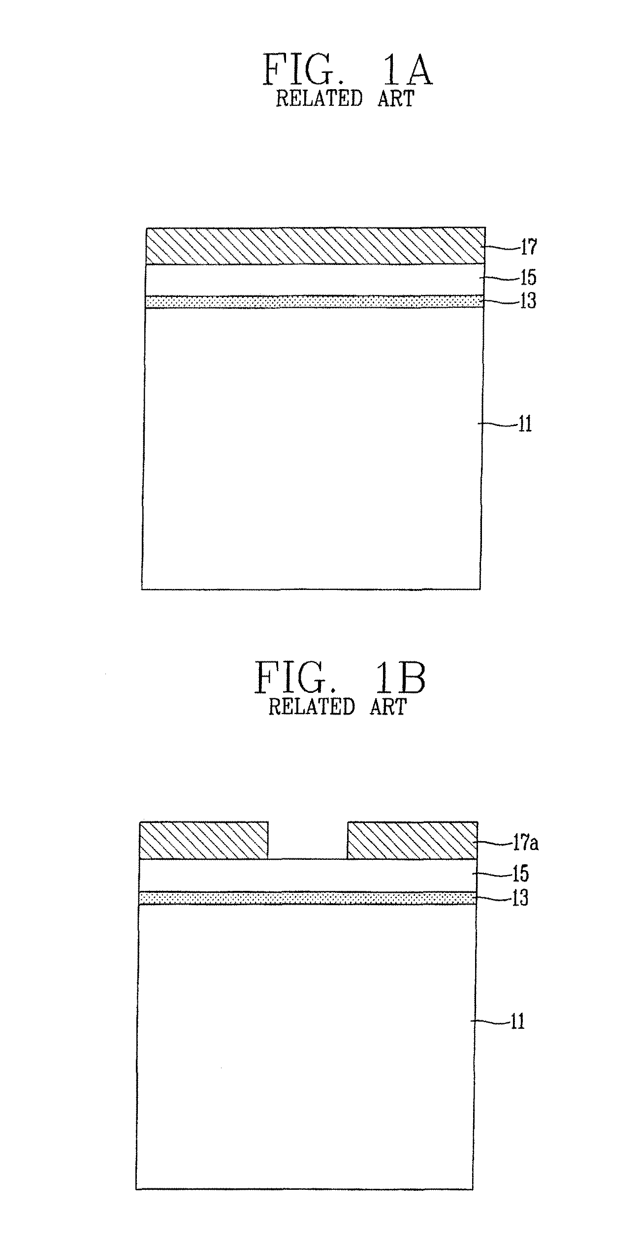
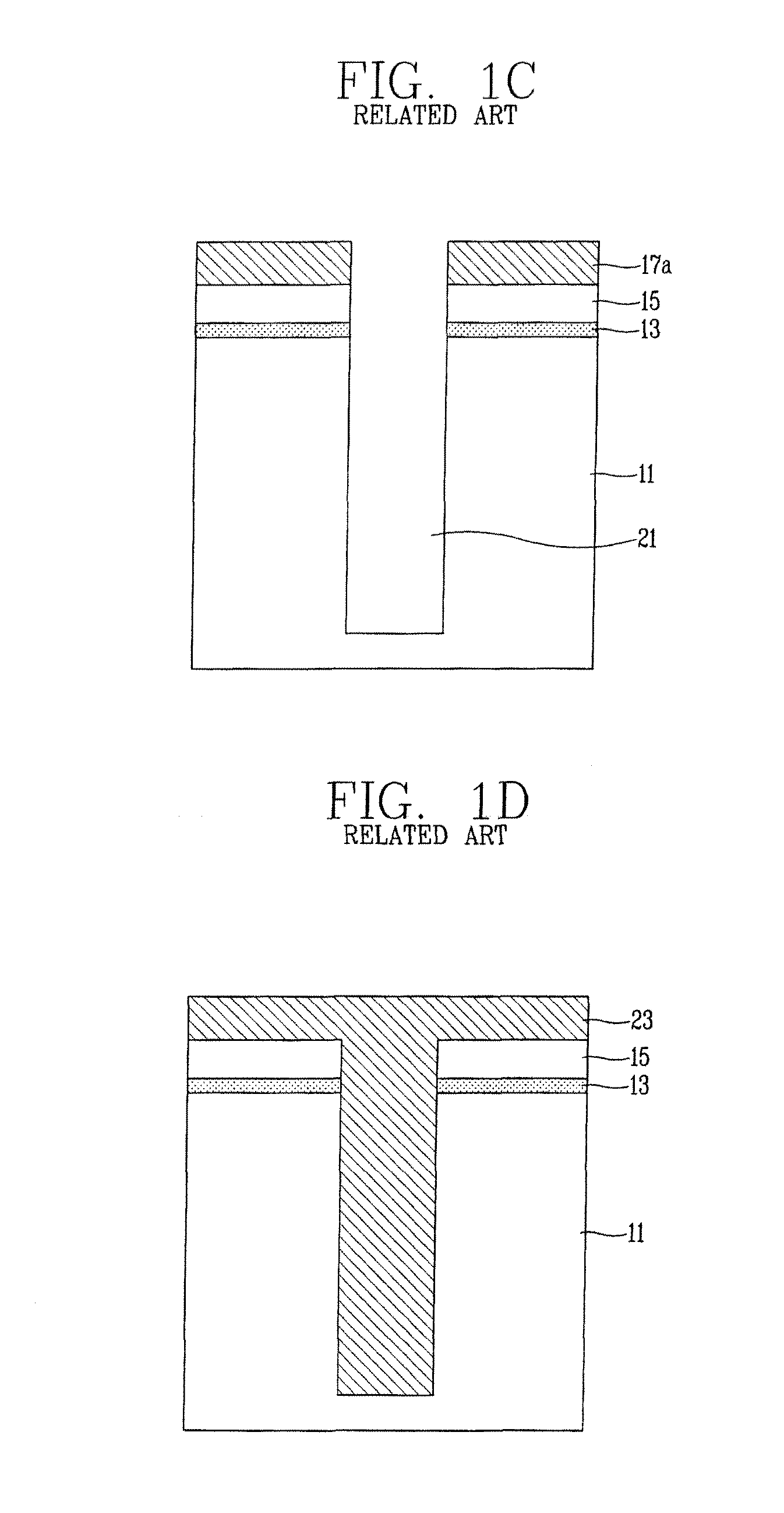
However, the method of forming the element isolation structure of the semiconductor device according to the related art has several problems as follows.
However, a defective coating may be caused during a photolithography process for forming the shallow trench, resulting in giving rise to a problem during the pattern forming process.
That is, upon exposure of the photosensitive film, the exposed portion of the photosensitive film is physically transformed but the depth of the deep trench may interrupt the exposure of the entire photosensitive film within the deep trench.
Consequently, the bottom portion of the photosensitive film may remain unexposed.
Also, according to the related art method of forming the element isolation structure, when coating the photosensitive film for forming the shallow trench after forming the deep trench, since the photosensitive film is coated by a spin coating, a sufficient gap-filling is not made.
Accordingly, a void is generated, thereby causing a defective coating.
That is, since the deep trench is extremely deep in depth, the defective coating such as the void is caused, whereby a material such as the photosensitive film (PR) is not evenly filled up to the top of the entire substrate.

Method used


Image

  • Element isolation structure of semiconductor and method for forming the same
  • Element isolation structure of semiconductor and method for forming the same
  • Element isolation structure of semiconductor and method for forming the same

Examples


Embodiment Construction

[0040]Description will now be given in detail of an element isolation structure of a semiconductor device and a method for forming the same in accordance with exemplary embodiments according to the present disclosure, with reference to the accompanying drawings. For the sake of brief description with reference to the drawings, the same or equivalent components will be provided with the same reference numbers, and description thereof will not be repeated.

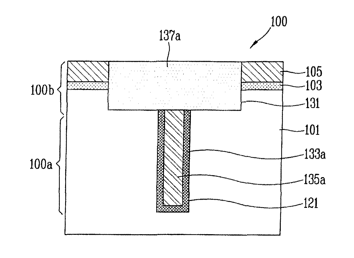
[0041]FIG. 2 is a sectional view of an element isolation structure of a semiconductor device in accordance with the present disclosure.

[0042]An element isolation structure 100 of a semiconductor device, as shown in FIG. 2, may include a semiconductor substrate 101 having an inactive region and an active region defined thereon, a deep trench 121 formed in the semiconductor substrate 101, a shallow trench 131 formed in the semiconductor substrate 101 and overlapped with the deep trench 121, an oxide pattern 133a and a polysilicon film ...


PUM


Abstract

Disclosed are an element isolation structure of a semiconductor device and a method for forming the same, the method including preparing a semiconductor substrate having an inactive region and an active region defined thereon, forming a first hard mask on the semiconductor substrate, exposing the inactive region of the semiconductor substrate by patterning the first hard mask, forming a second hard mask on the entire surface of the semiconductor substrate including the first hard mask, forming a deep trench in the semiconductor substrate by patterning the second hard mask and the semiconductor substrate, removing the patterned second hard mask, forming a shallow trench overlapped with the deep trench by patterning the semiconductor substrate using the first hard mask as a mask, forming an insulation film on the entire surface of the substrate including the shallow trench and the deep trench, filling the shallow trench and the deep trench by forming an element isolation film on the insulation film, and forming an element isolation film pattern in the deep trench and the shallow trench by selectively removing the element isolation film.

Description

CROSS-REFERENCE TO RELATED APPLICATION[0001]Pursuant to 35 U.S.C. §119(a), this application claims the benefit of earlier filing date and right of priority to Korean Application No. 10-2010-0070198, filed on Jul. 20, 2010, the contents of which is incorporated by reference herein in its entirety.BACKGROUND OF THE INVENTION[0002]1. Field of the Invention[0003]The present disclosure relates to an element isolation of a semiconductor device, and particularly, to an element isolation structure of a semiconductor, capable of forming an element isolation structure by using a deep trench and a shallow trench without any defect, and a method for forming the same.[0004]2. Background of the Invention[0005]Recently, element isolations for high voltage devices, among semiconductor devices, are divided into a junction isolation method and a deep trench isolation method. In recent time, the element isolation is achieved by the deep trench isolation for size reduction and improvement of isolation ...

Claims


Application Information

Patent Timeline
Patent Type & Authority Patents(United States)
IPC IPC(8): H01L29/06H01L21/762
CPCH01L21/76232
Inventor KANG, YANG-BEOM
Owner KEY FOUNDRY CO LTD
Learn More