Mass velocity sensor device and method for remote monitoring and visual verification of fluid velocity

a mass velocity sensor and fluid velocity technology, applied in liquid/fluent solid measurement, volume metering, instruments, etc., can solve the problems of low flow range sensitivity, achieve easy maintenance and adjustment, improve accuracy, and reduce resolution

Inactive Publication Date: 2014-11-27
FLUIDICS HAWAII
View PDF25 Cites 13 Cited by
  • Summary
  • Abstract
  • Description
  • Claims
  • Application Information

AI Technical Summary

Benefits of technology

[0008]In one preferred embodiment, a substantially clear sealed lid mounting structure that is separable and affixed to the channel body fixture allows for easy maintenance and adjustment and replacement of the spring as well as adjustment of a pre-load that works to change range of operation. In one implementation, adding a stiffer spring constant or force allows for a decrease in the resolution of a fixed scale so imprinted or affixed to the outside of the lid mounting structure. Moreover, an appendage can be mounted to the obstruction. Preferably, the appendage is curved so as to follow a prescribed path into a curved lid receiver pocket built into the lid mounting structure. In some embodiments, an electronic environment sensor that is additionally affixed to this lid allows wirelessly enabled remote monitoring of the mass velocity through the aperture. When the substantially hollow plastic appendage is pushed up into the receiver pocket, it works to displace fluid within the lid and allows an indirect sensing of velocity while simultaneously affords a visible confirmation of velocity of the mass within the channel body fixture through the aperture. By changing the electronic sensing means to optical sensing means provides other modes of electronic monitoring.
[0009]One preferred embodiment of the invention comprises a restriction or aperture that is sealed in one direction by way of a flap that is spring loaded in one direction. This flap pivots about an axis of a shaft that is perpendicular to the flow axis and is housed in a lid that allows a protrusion so affixed to the back of the flap to protrude out of the body of the back check valve body. The obstruction in this embodiment is the flap seal that allows flow of fluid in only one direction through the aperture. The flap is located in the flow stream of a fluid that is mounted as to rotate about a shaft whose axis is perpendicular to the flow direction. The obstruction is so designed so as to resist debris and fouling. Resistance to the rotation about the shaft is regulated by springs that may or may not be coaxial with the shaft. There is an adjustable flap swing limit. The spring or set of springs allow calibration of the amount of rotation relative to the flow. A stiffer spring would restrict flow ranges to higher flow velocities. A weaker spring would result in lower flow range sensitivity.
[0010]In one preferred embodiment the restriction is mounted in a clear plastic material so it is in the flow stream of the fluid. Springs that are co-axial with the shaft apply a constant force that opposes rotation of the restriction when the fluid is flowing in one direction. The clear mounting structure has an opening that allows an appendage affixed to the restriction within the flow to be viewed as it moves in relation to the restriction rotation. As fluid flow increases the appendage moves into the clear opening in clear view of observers no matter what viewing angle. It is a feature of this invention that viewing the flow rate from a distance is made easier. Electronic and optical position sensing solutions enable electronic transduction of flow data in both analog and digital form.

Problems solved by technology

The obstruction in this embodiment is the flap seal that allows flow of fluid in only one direction through the aperture.
A weaker spring would result in lower flow range sensitivity.

Method used


Image

  • Mass velocity sensor device and method for remote monitoring and visual verification of fluid velocity
  • Mass velocity sensor device and method for remote monitoring and visual verification of fluid velocity
  • Mass velocity sensor device and method for remote monitoring and visual verification of fluid velocity

Examples


Embodiment Construction

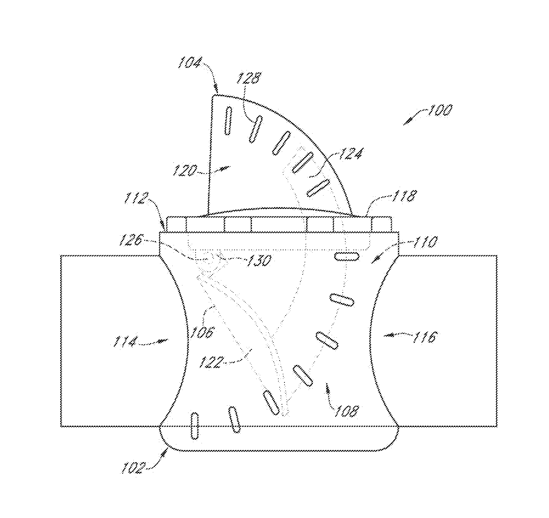
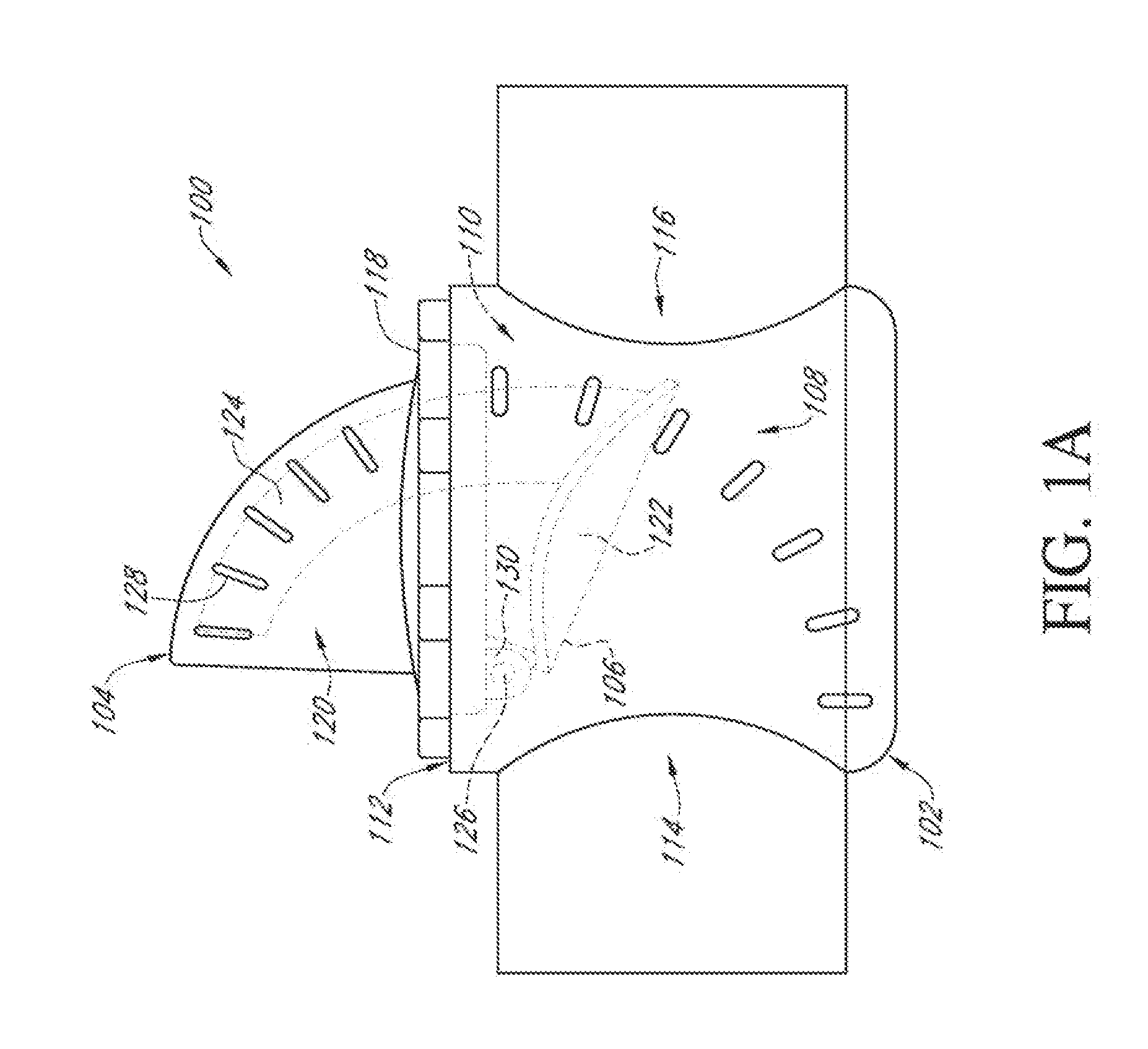
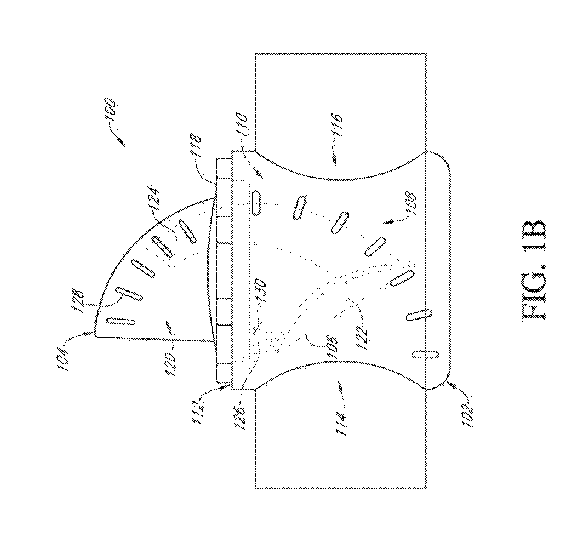
[0022]Reference will now be made to the drawings wherein like numerals refer to like parts throughout. FIGS. 1A and 1B illustrate a flow sensor assembly 100 according to one embodiment of the present invention. The flow sensor assembly 100 generally comprises a mounting body 102, a protruding lid 104 extending upwardly above the mounting body 102, and a pivotable obstruction member 106 disposed inside the mounting body 102. The mounting body 102 is configured with sidewalls 108 defining a receptacle 110 having an upper opening 112, and fluid inlet 114 and outlet 116 ports disposed on opposing sides of the receptacle 110. The mounting body 102 can be positioned in a flow stream, such as fitted to a conventional pipe or channel segment using fittings and methods known in the art. The protruding lid 104 has a base rim 118 and a receiver pocket 120 extending upwardly from the base rim 118. The base rim 118 is sealingly engaged with the mounting body 102 using screw type fasteners or oth...


PUM


Abstract

A wireless multi-range, mass velocity sensor assembly for remote monitoring with direct on-site visual validation of mass velocity is provided. In certain implementations, the sensor assembly comprises a channel body fixture, an obstruction mounted within an aperture formed in the inlet or outlet of the channel body fixture, and an arcuate indicator that protrudes above the fluid flow path and provides clear visual readout of the flow velocity. In some implementations, the sensor assembly can be easily adapted for existing back check valve and other back flow prevention devices.

Description

INCORPORATION BY REFERENCE TO ANY PRIORITY APPLICATIONS[0001]Any and all applications for which a foreign or domestic priority claim is identified in the Application Data Sheet as filed with the present application are hereby incorporated by reference under 37 CFR 1.57.BACKGROUND OF THE INVENTION[0002]1. Field of the Invention[0003]This invention generally relates to fluid flow sensing devices, and more particularly, relates to an in-line fluid flow sensor assembly designed to provide remote monitoring and visual verification of fluid flow through various fluid piping systems.[0004]2. Description of the Related Art[0005]Flow rates of fluids, gas, and loose solids are a measure of interest in plumbed, pumped, piped and channelized flow streams. In some plumbing systems, these flow streams can stretch over great distance and monitoring of the plumbing subsections become difficult. Various devices have been developed to measure in-line fluid flow in pipes and other channel systems. Flo...

Claims


Application Information

Patent Timeline
Patent Type & Authority Applications(United States)
IPC IPC(8): G01P5/06G01P1/08
CPCG01P1/08G01P5/065G01F1/28G01F15/063G01P5/04
Inventor DEVERSE, RICHARDCHAVEZ-PARDINI, MICK
Owner FLUIDICS HAWAII
Why Eureka
Try Eureka