
Rotation-angle detection device, image processing apparatus, and rotation-angle detection method

a detection device and image processing technology, applied in the direction of electrical/magnetically converting sensor output, electronic commutators, instruments, etc., can solve the problems of calibration process, phase angle deviation, sensor output signal error,

Active Publication Date: 2014-11-27
RICOH KK
View PDF2 Cites 44 Cited by
  • Summary
  • Abstract
  • Description
  • Claims
  • Application Information

AI Technical Summary

Benefits of technology

This invention relates to a device and method for detecting the rotation angle of a rotor. The device includes a unit that adjusts the amplitude of multiple detection signals from rotation detection units and generates corrected signals that have different phases. The device also includes a unit that generates two vector component signals that are perpendicular to each other by adding and subtracting the corrected signals. Another unit performs adjustment to match the amplitudes of the vector component signals. The device searches for the rotation angle of the rotor based on the vector represented by the vector component signals. The technical effects of this invention include improved accuracy in detecting the rotation angle of a rotor and improved accuracy in measuring the rotation angle of a rotor in a non-contact way.

Problems solved by technology

However, in conventional rotation-angle detection devices that use magnetic sensors, errors occur in the sensor output signals due to the difference between the sensitivities of the magnetic sensors used in the rotation-angle detection device, deviation of the phase angle due to the error in the assembly of the magnetic sensor in the rotator, and deviation of the magnetization of magnets.
However, the conventional technique described in Japanese Patent Application Laid-open No. 2004-325140 has a problem in that, as the calibration operation is performed after the rotation-angle detection device is assembled, the costs are increased due to a calibration process required after the rotation-angle detection device is assembled.

Method used


Image

  • Rotation-angle detection device, image processing apparatus, and rotation-angle detection method
  • Rotation-angle detection device, image processing apparatus, and rotation-angle detection method
  • Rotation-angle detection device, image processing apparatus, and rotation-angle detection method

Examples


first embodiment

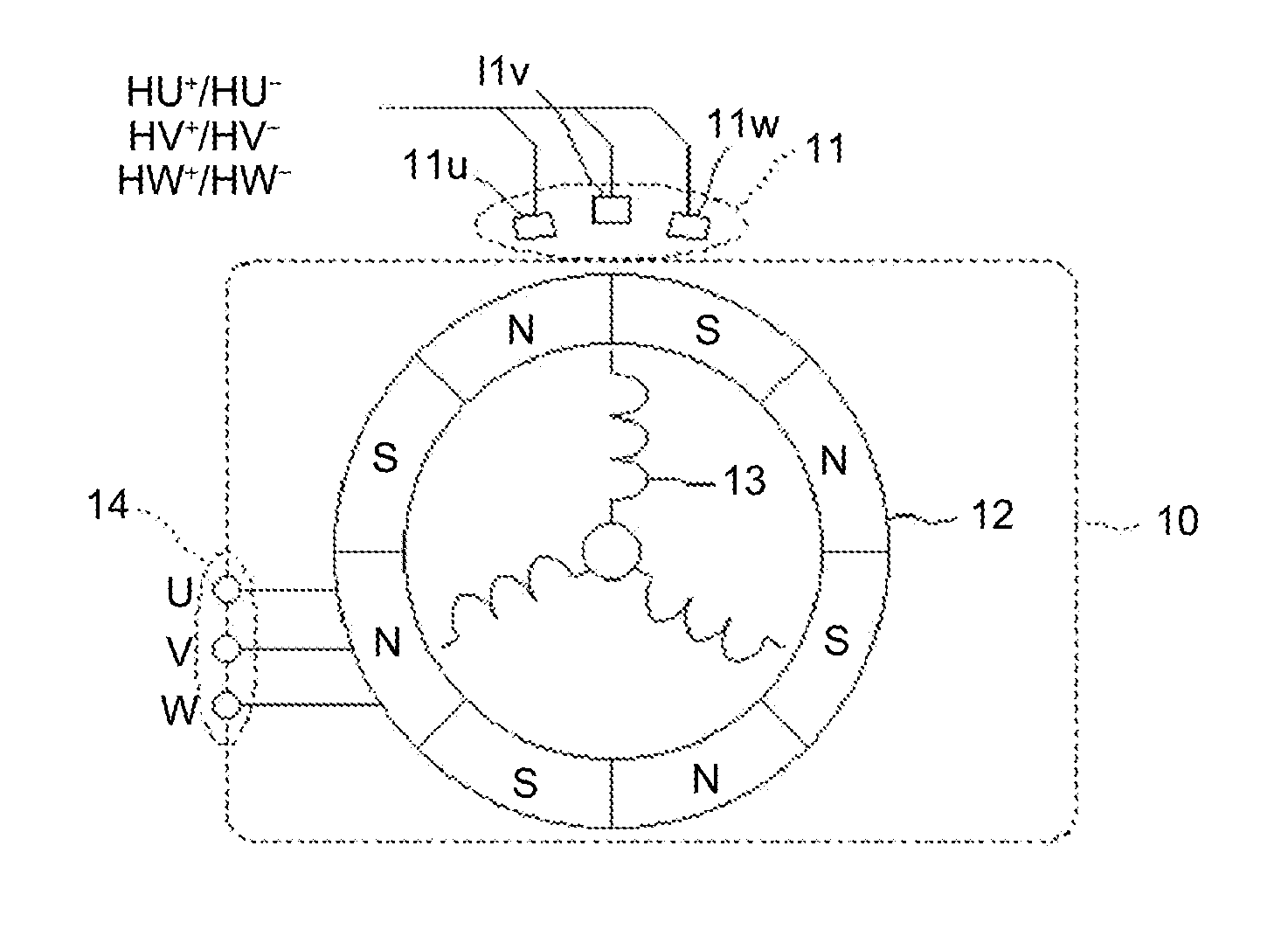
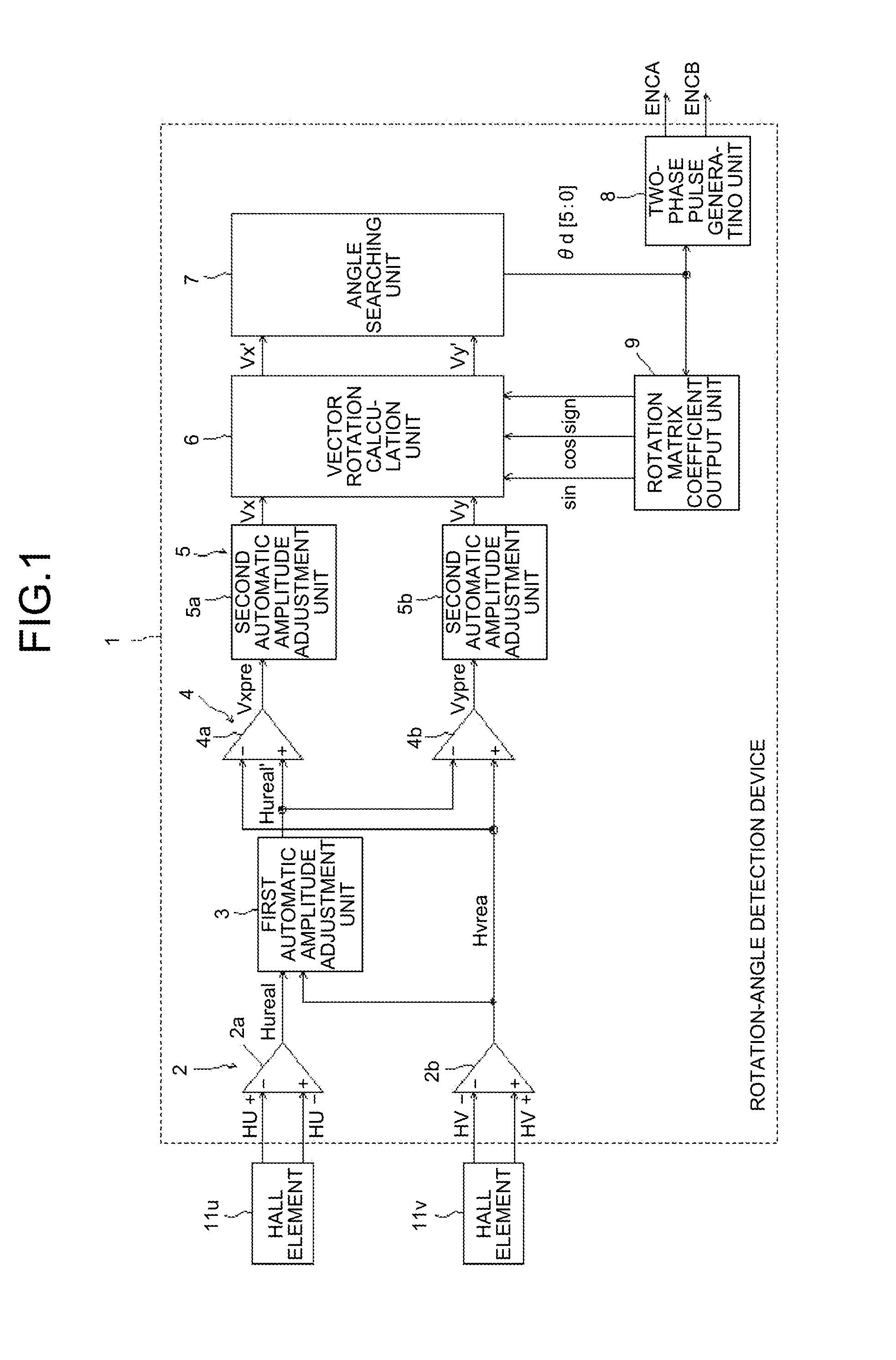
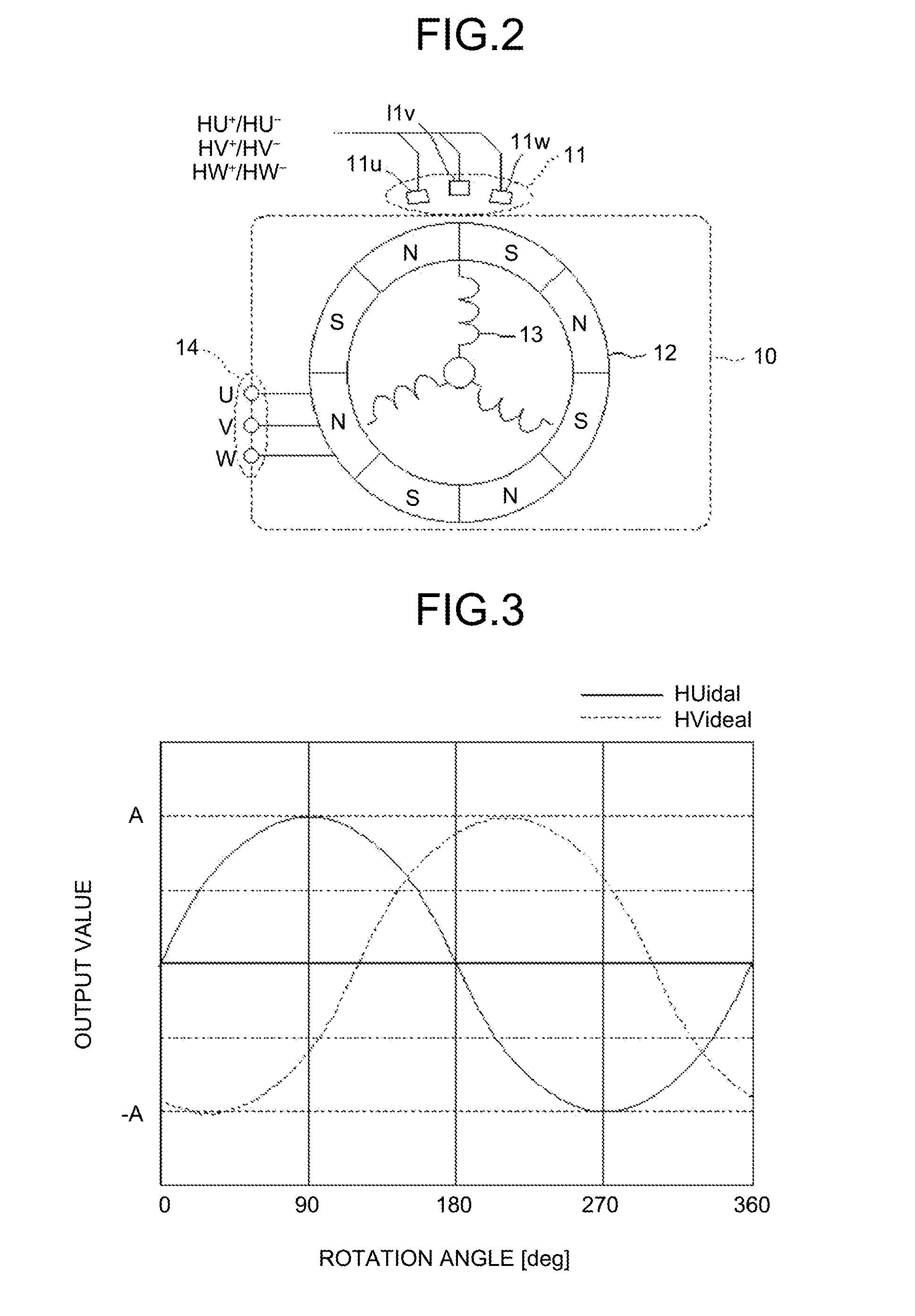
[0039]FIGS. 1 to 21 are diagrams that illustrate a first embodiment of a rotation-angle detection device, an image processing apparatus, and a rotation-angle detection method according to the present invention, and FIG. 1 is a circuit configuration diagram of a rotation-angle detection device 1 that uses the first embodiment of the rotation-angle detection device, the image processing apparatus, and the rotation-angle detection method according to the present invention.

[0040]In FIG. 1, the rotation-angle detection device 1 includes a differential unit 2, a first automatic amplitude adjustment unit 3, a vector generation unit 4, a second automatic amplitude adjustment unit 5, a vector rotation calculation unit 6, an angle searching unit 7, a two-phase pulse generation unit 8, and a rotation matrix coefficient output unit 9.

[0041]Out of U-phase, V-phase, and W-phase differential signals HU+ / HU−, HV+ / HV−, and HW+ / HW− that are output from Hall elements (rotation detection units) 11u, 11...


PUM


Abstract

A rotation-angle detection device includes: an amplitude adjustment unit that performs correction to match amplitude values of multiple detection signals output from multiple rotation detection units to output corrected signals, the rotation detection units changing outputs in accordance with a rotation angle of a rotor and being provided such that the rotation detection units output the detection signals having different phases; a vector generation unit that performs addition and subtraction on two signals out of the corrected signals to generate two vector component signals that are perpendicular to each other; an amplitude correction unit that performs correction to match amplitudes of the two vector component signals to output corrected vector component signals; and a rotation-angle searching unit that searches for the rotation angle of the rotor on basis of a vector that is represented by the two corrected vector component signals to output a detection angle.

Description

CROSS-REFERENCE TO RELATED APPLICATIONS[0001]The present application claims priority to and incorporates by reference the entire contents of Japanese Patent Application No. 2013-108540 filed in Japan on May 23, 2013.BACKGROUND OF THE INVENTION[0002]1. Field of the Invention[0003]The present invention relates to a rotation-angle detection device, an image processing apparatus, and a rotation-angle detection method.[0004]2. Description of the Related Art[0005]In image processing apparatuses, such as printers, facsimile machines, copiers, scanners, or multifunction peripherals, a driving mechanism is driven by a drive motor so that each of necessary units is driven at a predetermined speed for image processing, such as an image reading operation or image forming operation.[0006]Conventionally, in order to drive and rotate a rotator, such as a drive motor, at an intended speed, a sensor is provided around the rotator so as to output a signal that changes in a sine-wave pattern in accord...

Claims


Application Information

Patent Timeline
Patent Type & Authority Applications(United States)
IPC IPC(8): G01D5/14G01D18/00G01D5/244H02P6/16
CPCG01D18/00G01D5/142G01D5/145G01D5/2448
Inventor KAWASE, TATSUYA
Owner RICOH KK
Learn More