
Electrostatic detecting circuit and method thereof

a detection circuit and electrostatic technology, applied in the field of protective circuits, can solve the problems of inability to predict and record where the electrostatic current is hidden, electrical circuits lack good electrostatic protection recording mechanisms, and inability to provide good protection for circuits, etc., to achieve the effect of increasing protection capabilities

Inactive Publication Date: 2014-11-27
RAYDIUM SEMICON
View PDF7 Cites 2 Cited by
  • Summary
  • Abstract
  • Description
  • Claims
  • Application Information

AI Technical Summary

Benefits of technology

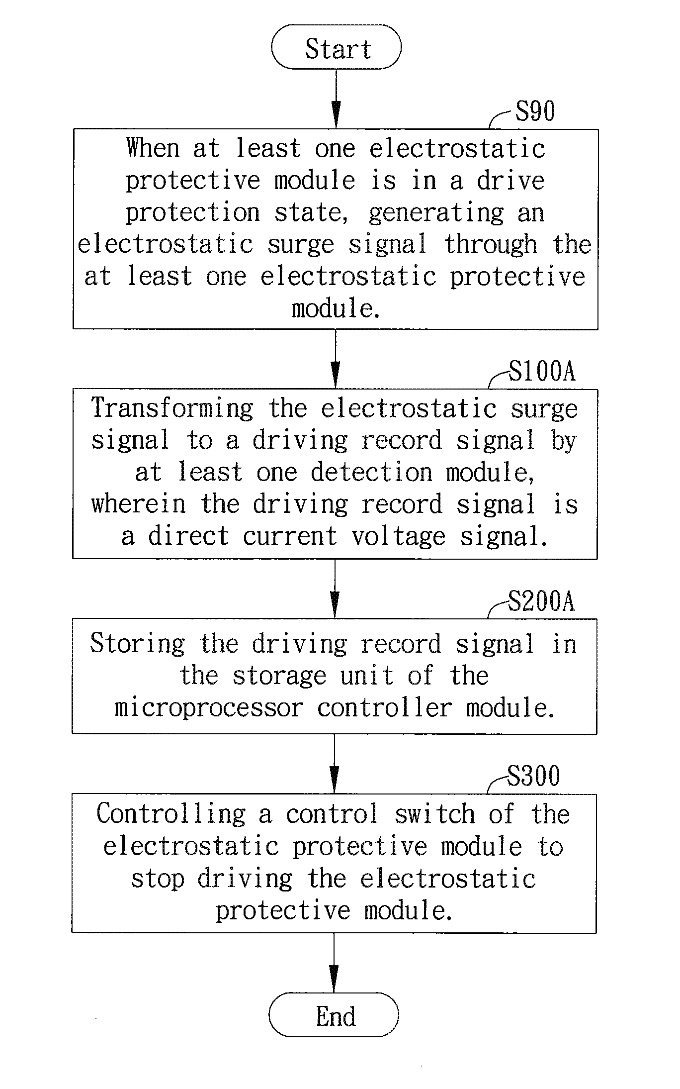
The present invention provides an electrostatic detecting circuit with a protection recording mechanism to increase protection capabilities. The circuit detects the driving status of the electrostatic protective module and outputs a driving record signal. The circuit path and protection positions of the protection circuit are recorded. The microprocessor controller module can read the driving record signal to build an electrostatic protection diagram. The electrostatic protection circuit can adjust certain blocks of the protective components of the electronic component to selectively switch off the protective components or adjust protection levels thereof in order to accomplish the effect of detecting electrostatic protection and authentication.

Problems solved by technology

However, in actual conditions, researchers are only able to determine the placement location and protection levels of the electrostatic components from experience, and are not able to predict and record where the electrostatic current is hidden.
In other words, present electrical circuits lacks good electrostatic protection recording mechanisms and consequently are not able to provide good protection for circuits.
In addition, out of precaution, researchers typically place vast amounts of ESD components to protect the electrical circuits.
However, not all of the ESD components are necessary and thus help to incur unnecessary costs.
Accordingly to the above mentioned problems, designs allowing the recordation of electrostatic protection positions in order to increase circuit protection capabilities have currently become a pressing issue.

Method used


Image

  • Electrostatic detecting circuit and method thereof
  • Electrostatic detecting circuit and method thereof
  • Electrostatic detecting circuit and method thereof

Examples


Embodiment Construction

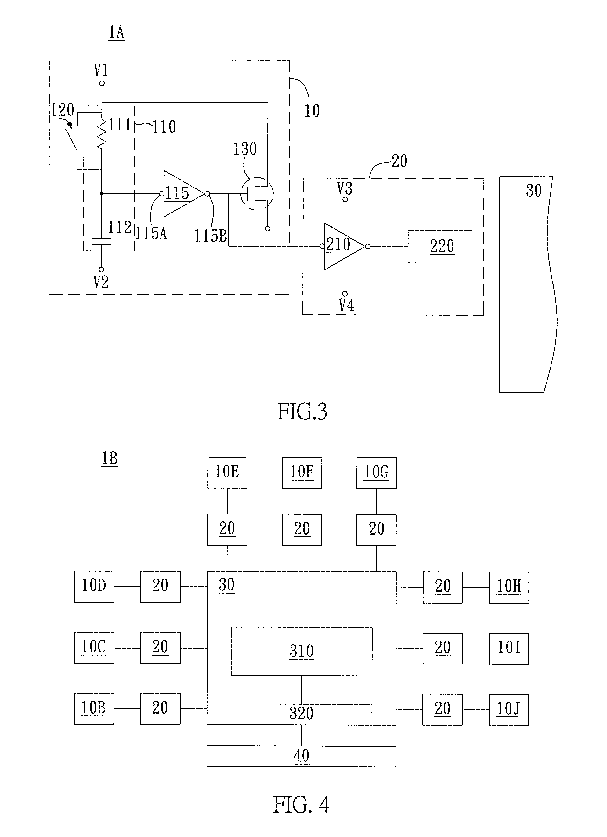
[0021]According to an embodiment of the present invention of an electrostatic detecting circuit, the electrostatic detecting circuit can record electrostatic protection positions. In the present embodiment, the electrostatic detecting circuit is an electrostatic detecting circuit of display devices; however, the electrostatic detecting circuit is not limited to display devices. In other different embodiments, the electrostatic detecting circuit may be applicable to computers, electronic mobile devices, media players, or any other electronic devices without any particular restrictions.

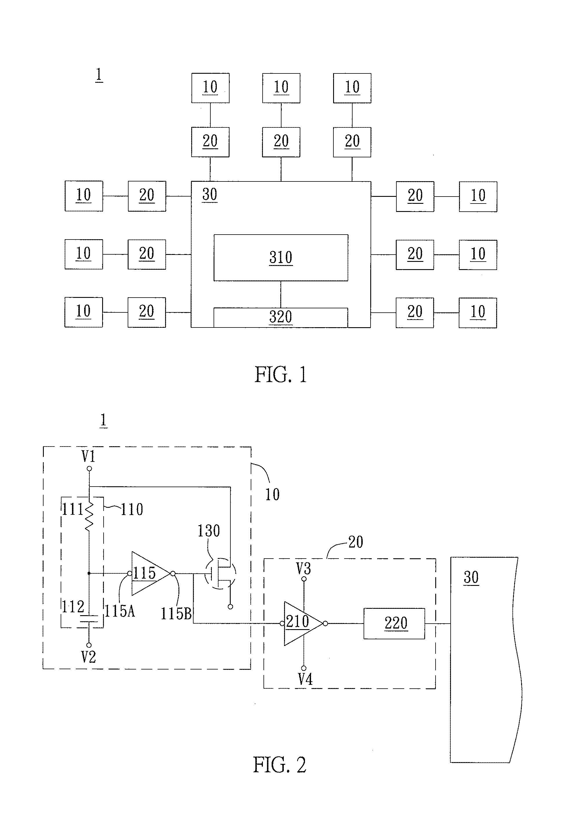
[0022]Please refer to FIG. 1. FIG. 1 is an illustration of an embodiment of the electrostatic protection circuit of the present invention. As shown in FIG. 1, the electrostatic detecting circuit 1 includes at least one electrostatic protective module 10, at least one detection module 20, and a microprocessor controller module 30. In the present embodiment, the detection module(s) 20 are respectively con...


PUM


Abstract

An electronic detecting circuit includes at least one electrostatic protective module, at least one detection module, and a microprocessor controller module. The at least one detection module is respectively connected to the at least one electrostatic protective module, and the at least one detection module generates a driving record signal according to a driving state of the at least one electrostatic protective module. The microprocessor controller module is coupled with the at least one detection module, wherein the microprocessor controller module records the driving record signal when the at least one detection module transmits the driving record signal to the microprocessor controller module.

Description

BACKGROUND OF THE INVENTION[0001]1. Field of the Invention[0002]The present invention generally relates to a protective circuit with protective electrostatic recording capabilities; particularly, the present invention relates to an electrostatic detection module for increasing electrostatic protection of displays and having a recording mechanism.[0003]2. Description of the Related Art[0004]In a conventional circuit, researchers place ESD components (Electrostatic Discharge components) to protect circuit chips in order to prevent damage to the circuit chips from electrostatic attacks. However, in actual conditions, researchers are only able to determine the placement location and protection levels of the electrostatic components from experience, and are not able to predict and record where the electrostatic current is hidden.[0005]It should be noted that researchers improve on the electrostatic protection mechanism only after the electronic component and circuit chip has been damaged...

Claims


Application Information

Patent Timeline
Patent Type & Authority Applications(United States)
IPC IPC(8): G01R29/12
CPCG01R29/12G01R31/002G01N27/60G01R5/28G01R15/165G01R19/0023G01R29/24G01R31/12
Inventor LIU, CHENG-CHIN
Owner RAYDIUM SEMICON
Learn More