Backlight unit and liquid-crystal display device

Inactive Publication Date: 2014-11-27
SHARP KK
View PDF2 Cites 5 Cited by
  • Summary
  • Abstract
  • Description
  • Claims
  • Application Information

AI Technical Summary

Benefits of technology

The present invention provides a backlight unit and a liquid-crystal display device that can reduce brightness unevenness caused by thermal stress, optical sheet deflection or wrinkling, and leakage light. This improves the efficiency of the light output from the light source unit and enhances the display quality of the device.

Problems solved by technology

Conventionally, the edge light type backlight unit has had difficulty, due to its structure in which light enters the light guide plate from a side surface of the light guide plate, in emitting large planar light having a uniform brightness distribution.
There is a case, however, where light emitted from the light source unit fails to enter the light guide plate (leakage light is generated) and directly enters a liquid-crystal panel unit.
At a portion of the liquid-crystal panel unit where the leakage light has entered, brightness unevenness may occur, which is a phenomenon that brightness becomes higher at the portion than at any other portion of the liquid-crystal panel unit, resulting in deterioration in quality.
Furthermore, in the edge light type backlight unit, it is likely that a positional misalignment between the light source unit and the light guide plate leads to a decrease in brightness of emitted light and the occurrence of brightness unevenness.

Method used


Image

  • Backlight unit and liquid-crystal display device
  • Backlight unit and liquid-crystal display device
  • Backlight unit and liquid-crystal display device

Examples


first embodiment

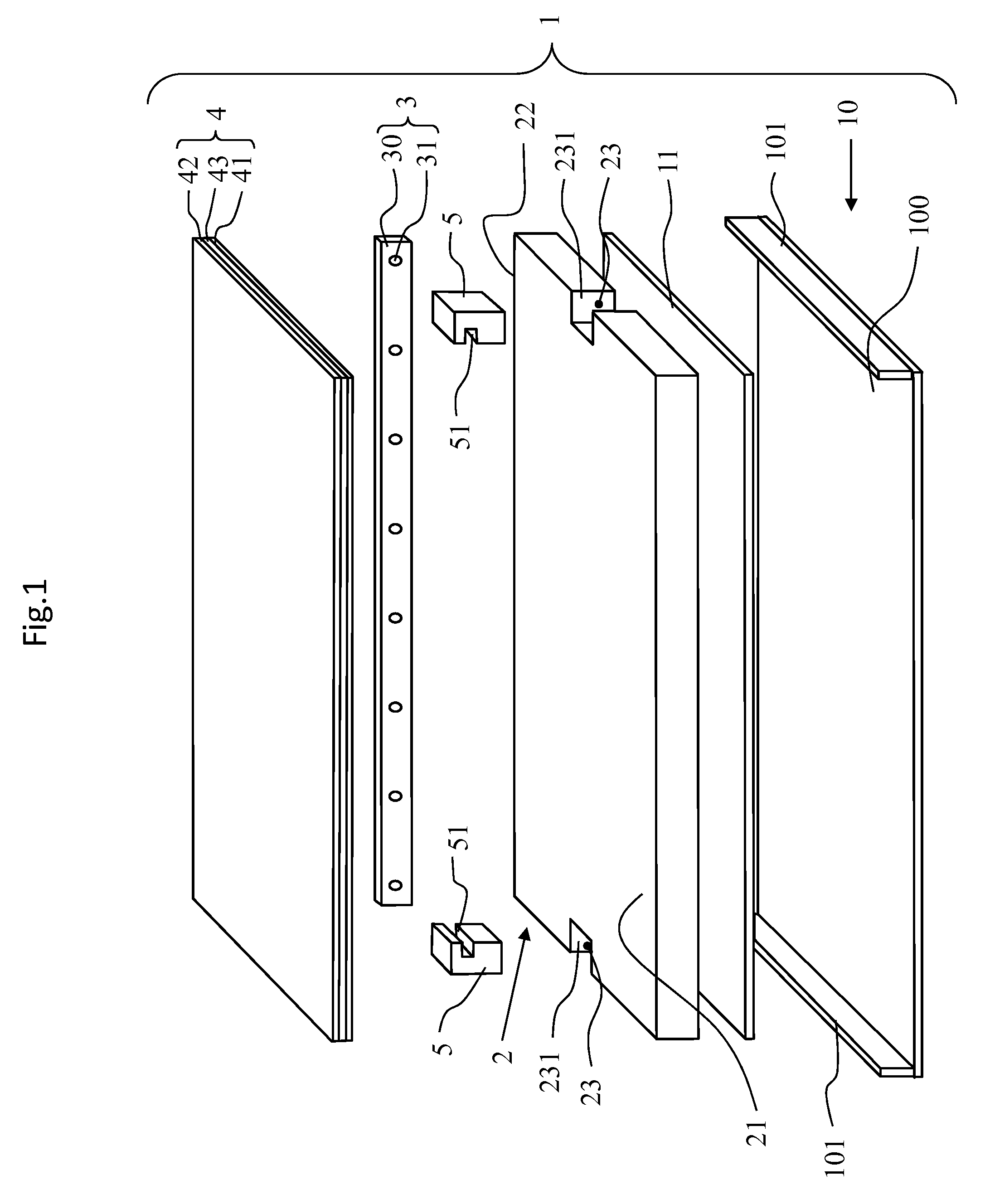
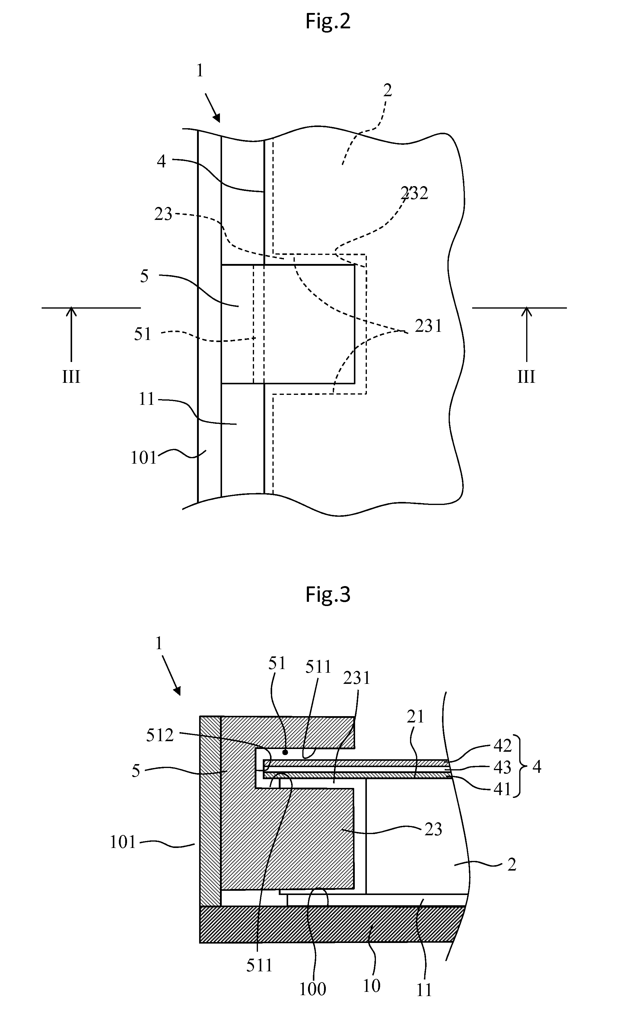
[0035]FIG. 1 is an exploded perspective view of one example of a backlight unit according to the present invention. In a backlight unit shown in FIG. 1, it is assumed that an upper side of the plane of the figure is a front side, and a lower side of the plane of the figure is a rear side. Furthermore, unless otherwise specified, the following description refers to the front side or the rear side with reference to a state shown in FIG. 1.

[0036]As shown in FIG. 1, a backlight unit 1 is an illumination device that emits planar light such as for use as backlight for a liquid-crystal display device. The backlight unit 1 includes a back chassis 10, a reflection sheet 11, a light guide plate 2, a light source unit 3, an optical sheet 4, and a light guide plate positioning portion 5.

[0037]The back chassis 10 is a member rectangular in front view and has a bottom surface portion 100 in the shape of a rectangle. As shown in FIG. 1, in the backlight unit 1, from the rear side, the reflection s...

second embodiment

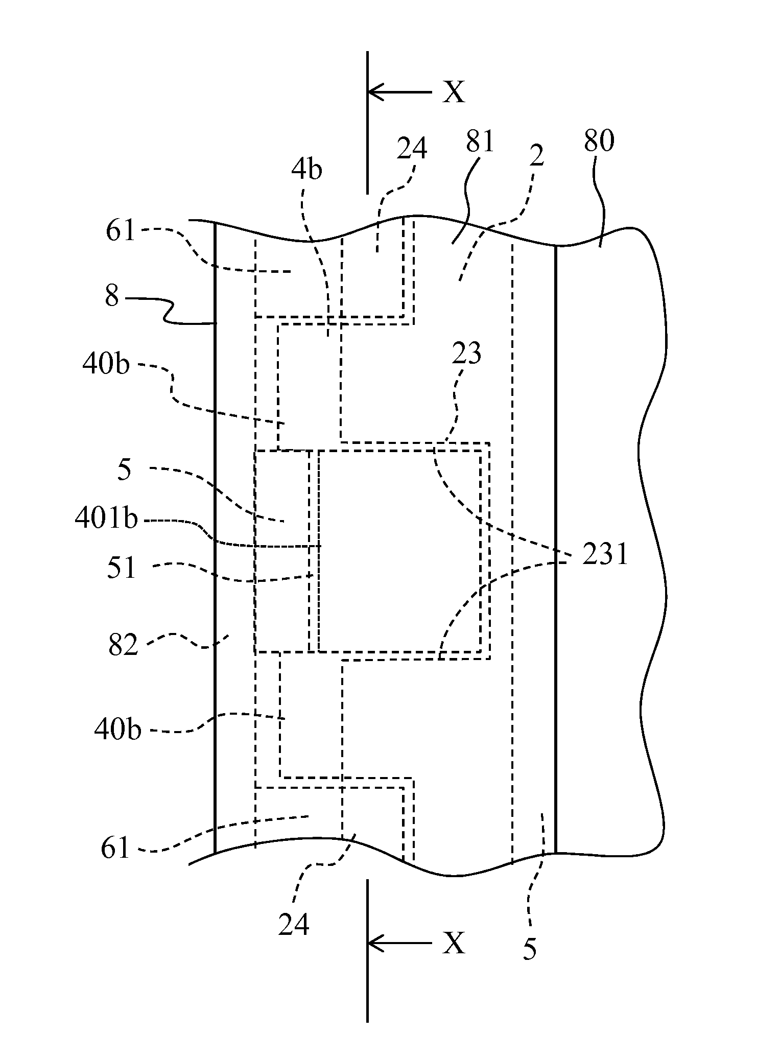
[0057]A description is given of another example of the backlight unit according to the present invention with reference to the appended drawings. FIG. 4 is a front view of another example of the backlight unit according to the present invention, FIG. 5 is an enlarged view of a vicinity of a light guide plate positioning portion of a backlight unit shown in FIG. 4, and FIG. 6 is a sectional view of the backlight unit shown in FIG. 5, as taken on line VI-VI. As shown in FIGS. 4 and 5, a backlight unit 1B has the same configuration as that of the backlight unit 1 shown in the first embodiment except for a light guide plate holding-down portion 6 that holds down each of end portions of a light guide plate 2 in a long length direction thereof and an optical sheet 4b, and constituent components that are practically the same as those of the backlight unit 1 are indicated by the same reference characters.

[0058]The backlight unit 1B according to the present invention includes the light guide...

third embodiment

[0066]A description is given of a liquid-crystal display device using the backlight unit according to the present invention with reference to the appended drawings. FIG. 7 is an exploded perspective view of a liquid-crystal display device according to the present invention, and FIG. 8 is a rear view of the liquid-crystal display device according to the present invention in a state where a back chassis has been removed therefrom. FIG. 9 is an enlarged view of a light guide plate positioning portion of the liquid-crystal display device according to the present invention, and FIG. 10 is a sectional view of the liquid-crystal display device shown in FIG. 9, as taken on line X-X.

[0067]As shown in FIG. 7, a liquid-crystal display device A includes a backlight unit 1B, a liquid-crystal panel unit 7, and an appearance frame 8. In the liquid-crystal display device A shown in FIG. 7, the backlight unit 1B shown in FIG. 4 is practically adopted while being partly changed so as to be suited for...


PUM


Abstract

To alleviate brightness unevenness arising from optical sheet bending or wrinkling, as well as brightness unevenness caused by light leakage, and improve light usage emitted by a light source unit, provided is a backlight unit (1) comprising a light guide plate alignment unit (5) which is positioned to maintain a given location with respect to a back chassis (10), latches with a depression part (23), and further comprising a depression part (51) which is formed such that a portion of an optical sheet (4) is inserted.

Description

TECHNICAL FIELD[0001]The present invention relates to an edge light type backlight unit and a liquid-crystal display device including the same.BACKGROUND ART[0002]A liquid-crystal display device includes a liquid-crystal panel unit and a backlight unit disposed behind the liquid-crystal panel unit, and the liquid-crystal panel unit modulates light from the backlight unit, thus causing a video image to be displayed on a front surface of the liquid-crystal panel unit.[0003]As the backlight unit used in the liquid-crystal display device, there is used a light guide plate type (edge light type) backlight unit including a light guide plate and a light source from which light is made to enter the light guide plate from a side surface of the light guide plate. The following describes such an edge light type backlight unit. The edge light type backlight unit includes a light source unit in which a plurality of LEDs are arranged in line, a light guide plate that receives, on a light receptio...

Claims


Application Information

Patent Timeline
IPC IPC(8): F21V8/00G02F1/1333
CPCG02B6/0016G02F1/133308G02B6/0091G02B6/0088G02F1/133322
Inventor IKUTA, JO
Owner SHARP KK
Why Eureka
Try Eureka