Organometallic-compound feeder

Inactive Publication Date: 2011-05-26
SUMITOMO CHEM CO LTD
View PDF5 Cites 3 Cited by
  • Summary
  • Abstract
  • Description
  • Claims
  • Application Information

AI Technical Summary

Benefits of technology

[0038]The use of the feeder of the present invention can supply the organometallic compound which is in a solid state at the ordinary temperature by allowing the compound to be entrained by the carrier gas at a more stable concentration and can increase the usage efficiency of the organometallic compound packed in the packing container.

Problems solved by technology

Once the partial consumption starts, the consumption of the organometallic compound in the portion is facilitated and then a path where the carrier gas easily flows is formed, since the organometallic compound has poor flowability.
As a result, the organometallic compound cannot be supplied stably into a reactor such as an MOCVD apparatus.
Therefore, when the organometallic compound which is in a solid state at the ordinary temperature is packed as it is, the carrier gas containing the organometallic compound at a stable concentration is not obtained for a long period of time, and the organometallic compound is not used efficiently.
However, there are various problems in methods for discharging the carrier gas.
The consumption of the solid organometallic compound proceeds sequentially from an inlet of the carrier gas, which results in problem that the consumption becomes non-uniform due to the distribution of flow rate near the portion where the carrier gas is discharged, as the consumption proceeds,
As a result, the gas which contains the organometallic compound at a desired concentration cannot be supplied stably into the reactor such as the MOCVD apparatus in spite of the fact that the solid organometallic compound is remained in the packing container.
This problem is more noticeable when the amount of the carrier gas introduced into the packing container is increased to conform to the increase in the size of the packing container which is packed with the solid organometallic compound and the increase in the supply amount per unit time of the carrier gas, which results from the increase in consumption amount of the organometallic compound due to the use of a larger reactor such as the MOCVD apparatus.
In other words, it is more difficult that the carrier gas containing the organometallic compound at a stable concentration is discharged for a long period of time, while the solid organometallic compound remained in the packing container is efficiently consumed.
However, clogging is caused by the solid organometallic compound when the opening size in the sintered metal or the porous plate is small, whereby drift occurs in the carrier gas which passes through the solid organometallic compound.
It is considered that this results in a cause of nonuniform consumption of the solid organometallic compound.

Method used


Image

  • Organometallic-compound feeder
  • Organometallic-compound feeder
  • Organometallic-compound feeder

Examples


example 1

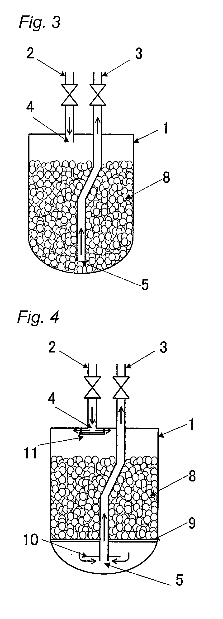
[0090]An organometallic compound feeder of the present invention was constructed which was similar to that shown in FIG. 4 except that a baffle plate was attached to a tip portion of a discharging tube, that is, a level of an outlet. A bottom portion of a packing container 1 was curved and the packing container 1 had a volume of about 1300 cm3 (an inner diameter: 108 mm, a height: 147 mm). A support plate 9 (a size of opening: 2 mm metal mesh) was placed at 26 mm from a bottommost position of the packing container. A distribution plate 11 (a disc-shaped flat plate: a diameter of 18 mm) was attached at the carrier gas inlet 4 in parallel to a top plate of the packing container 1 so that a distance between the top plate of the packing container and the distribution plate 11 was 3 mm, whereby the carrier gas was introduced in a direction almost vertical relative to the central axis of the container. Further, a carrier gas discharging tube 3 (an outer diameter 8 mm, an inner diameter 6 ...

example 2

[0095]The alumina spheres were allowed to carry TMI thereon in the same packing container 1 as that used in Example 1, in the same manner as that in Example 1 except that the diameter of the baffle plate 10 (the disc-shaped flat plate) which was attached to the tip portion of the carrier gas discharging tube 3 (the carrier gas outlet 5) was 50 mm.

[0096]The usage rate of TMI was determined in the same manner as that in Example 1. The results are shown in FIG. 8. The TMI concentration was kept stable until the usage rate reached about 87%, and then reduced.

example 3

[0097]The alumina spheres were allowed to carry TMI thereon in the same packing container 1 as that used in Example 1, in the same manner as that in Example 1 except that the diameter of the baffle plate 10 (the disc-shaped flat plate) which was attached to the tip portion of the carrier gas discharging tube 3 (the carrier gas outlet 5) was 80 mm.

[0098]The usage rate of TMI was determined in the same manner as that in Example 1. The results are shown in FIG. 9. The TMI concentration was kept stable until the usage ratio reached about 85%, and then reduced.


PUM

PropertyMeasurementUnit
Sizeaaaaaaaaaa
Sizeaaaaaaaaaa
Temperatureaaaaaaaaaa

Abstract

An organometallic compound feeder comprising a packing container into which an organometallic compound that is in a solid state at an ordinary temperature is to be packed and a carrier gas is to be fed to sublimate the organometallic compound further comprises:a support plate which is to hold the organometallic compound carried on an inert carrier in the packing container and which is to allow the carrier gas to pass therethrough,a carrier gas inlet in an upper portion of the packing container,a carrier gas outlet which is opened below the support plate in a bottom portion of the packing container, anda baffle plate which is attached between the support plate and the carrier gas outlet and is larger than an opening diameter of the carrier gas outlet, andthe feeder is configured so as to allow carrier gas to pass downward through the organometallic compound carried on the inert carrier packed on the support plate.

Description

TECHNICAL FIELD[0001]The present invention is related to an organometallic-compound feeder. Specifically, the present invention is related to an organometallic-compound feeder wherein: a carrier gas is supplied to an apparatus containing an organometallic compound which is in a solid state at an ordinary temperature, and preferably at an ordinary temperature and an ordinary pressure to prepare the carrier gas containing the organometallic compound at a more stable concentration and supply the prepared gas to an apparatus which uses the organometallic compound; and the carrier gas is prepared by using the organometallic compound contained in the apparatus at a higher availability, that is, the carrier gas can be prepared with a higher usage rate of the organometallic compound.BACKGROUND ART[0002]The organometallic compound is used as a material for epitaxial growth of a compound semiconductor. In particular, the organometallic compound is often used in the metalorganic chemical vapor...

Claims


Application Information

Patent Timeline
IPC IPC(8): B65B31/00
CPCC30B25/14C23C16/4481H01L21/02365H01L21/67017
Inventor ABE, TOSHIMITSU
Owner SUMITOMO CHEM CO LTD
Why Eureka
Try Eureka