Ink feeding member

Inactive Publication Date: 2004-10-07
BRIDGESTONE CORP
View PDF3 Cites 0 Cited by
  • Summary
  • Abstract
  • Description
  • Claims
  • Application Information

AI Technical Summary

Benefits of technology

0007] Accordingly, it is an object of the present invention to provide an ink feeding member which makes it possible to increase the amount of ink contained and lower the ink rema

Problems solved by technology

Hitherto, however, the urethane foam comparable in size to the ink tank (ink cartridge) has thus been used and, therefore, it has been difficult to increase the amount of ink contained in the t

Method used


Image

  • Ink feeding member
  • Ink feeding member
  • Ink feeding member

Examples


Example

Example and Comparative Example

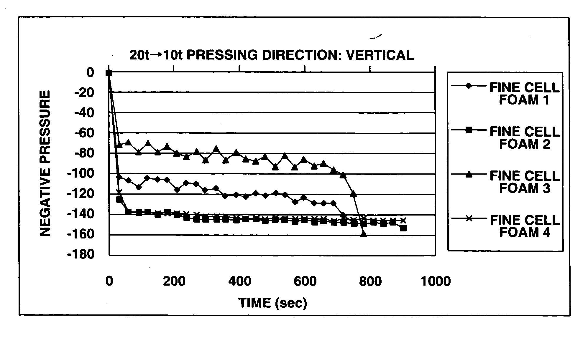
[0026] Polyether-based polyurethane foams having densities, quantities of cells, and ventilation volumes as shown in Table 1 were prepared.

1TABLE 1 Ventilation Quantity Density volume of cells Material (g / cm.sup.3) (cc / cm.sup.2 / sec) (pieces / inch) Comparative Example foam 0.056 80.0 60 Ultra fine cell foam 1 0.091 35.0 120 Ultra fine cell foam 2 0.106 10.2 150 Ultra fine cell foam 3 0.106 20.2 170 Ultra fine cell foam 4 0.117 13.0 180

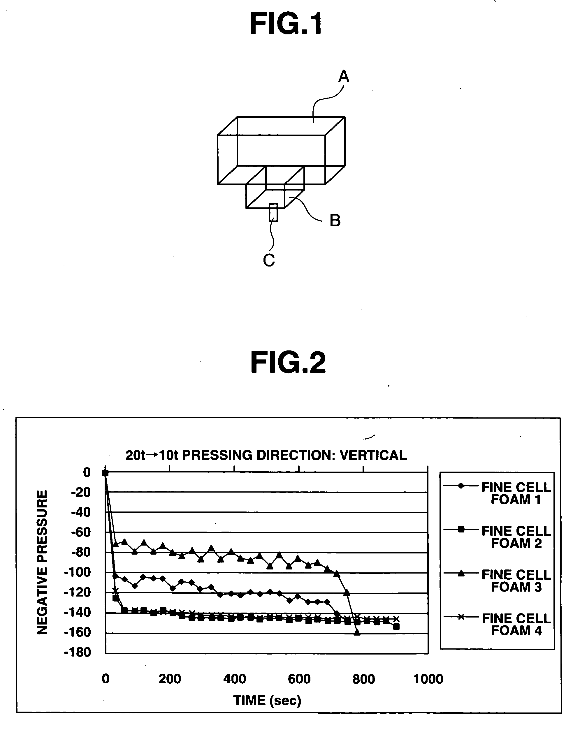
[0027] Next, each of hot pressed foams measuring 10 t.times.15.times.23 mm as shown in Table 2 was placed to fill a bottom portion (case lower portion B) of a case (case upper portion A: 23 t.times.50.times.23 mm; case lower portion B: 10 t.times.15.times.23 mm) shown in FIG. 1. In the figure, C denotes the ink discharge port. In the case of Comparative Example foam, the foam is placed to fill up the whole part of the case (namely, the case A and the case B). The filling with the foam was conducted as follows. First, the fo...


PUM


Abstract

An ink feeding member comprising an ink tank for storing an ink, and an ink discharge control material placed in the ink tank to close an ink discharge port of the ink tank and to partially fill the ink tank, characterized in that the ink discharge control material is comprised of an ultra fine cell foam or a hot press formed product thereof with a density of 0.06 g/cm<3 >or more, quantity of cells of 100/in or more, and a ventilation volume of 0.002 to 40 cc/cm<2>/ sec.

Description

[0001] The present invention relates to an ink feeding member which is used, particularly, for feeding an ink to a printing head.[0002] In recent years, there has been a remarkable progress in OA apparatuses, and, with respect to printers, there has been occurring a shift from the wire dot system and thermal transfer system to the ink jet system.[0003] In the ink jet system, it is a common practice to contain an ink holding member in an ink tank (ink containing vessel) in order to hold an ink uniformly in the tank.[0004] As the ink holding member, a polyurethane foam or a hot press formed product thereof is used. Conventionally, it has been practiced to pack the ink holding member densely into the tank and hold the ink in the cells of the ink holding member (a polyurethane foam or a hot press formed product thereof).[0005] Hitherto, however, the urethane foam comparable in size to the ink tank (ink cartridge) has thus been used and, therefore, it has been difficult to increase the a...

Claims


Application Information

Patent Timeline
IPC IPC(8): B41J2/175
CPCB41J2/17513B41J2/17556B41J2/17563B41J2/17596
Inventor YAMAMOTO, KAZUHIROKINOSHITA, HIDEYAYAMAGUCHI, NORIYUKI
Owner BRIDGESTONE CORP
Why Eureka
Try Eureka