Ring control node

Inactive Publication Date: 2006-01-31
FUJITSU LTD
View PDF7 Cites 8 Cited by
  • Summary
  • Abstract
  • Description
  • Claims
  • Application Information

AI Technical Summary

Benefits of technology

[0022]In light of the above problems, it is an object of the present invention to remove the prior art limitation on the number of nodes, wherein the maximum number of nodes which could be installed on one ring was 16, and to provide a ring control node that capitalizes on the advantages of the increase in line usage efficiency of the BLSR structure and can support a wide area with one ring.
[0023]Also, it is an object of the present invention to provide a BLSR ring system and nodes therefor that, when the scale of a ring system is expanded and the number of nodes installed within one ring is increased, makes fault recovery possible, within a suitable time frame, by realizing a speed increase of the throughput of path switching request signals in an increased number of intermediate nodes.
[0024]Further, it is an object of the present invention to provide a ring control node that, when a topology map mismatch occurs in a given node within a ring, makes possible reliable and rapid topology map repair, by providing a topology map structure which makes it possible to detect the such errors.
[0025]Further still, it is an object of the present invention to provide a ring control node that can utilize as much as possible and without changes a format based on the APS protocol for BLSR, and thereby satisfy the demand for consistency with existing BLSR ring systems.

Problems solved by technology

However, in the prior art BLSR ring system there are the following problems.
In such a case, a BLSR control used within one ring can be troublesome, and there is the problem that, since it becomes necessary to introduce a new device to interconnect each of the rings, the network equipment and network management costs increase significantly.
As a result, it is impossible to capitalize on the advantages of improving the line usage efficiency of the BLSR structure and to satisfy the customers' strong demand to be able to support a wide area with one ring.
Secondly, if the scale of a network is enlarged and the number of nodes installed within one ring is increased, the time taken from detection of a fault till execution of the path switching operation increases in proportion to the number of nodes.
As a result, a new problem occurs in that fault recovery cannot be achieved within a suitable time frame.
Thirdly, in the usage of a topology map by way of BLSR control, there is the possibility of the following problem occurring under certain conditions.
As a result, the path switching conditions are never realized in either of the node 31 or node 34, the ring system remains in a receiving standby state, and the mismatch alarm is not generated, therefore this causes major problems.

Method used


Image

  • Ring control node
  • Ring control node
  • Ring control node

Examples


Embodiment Construction

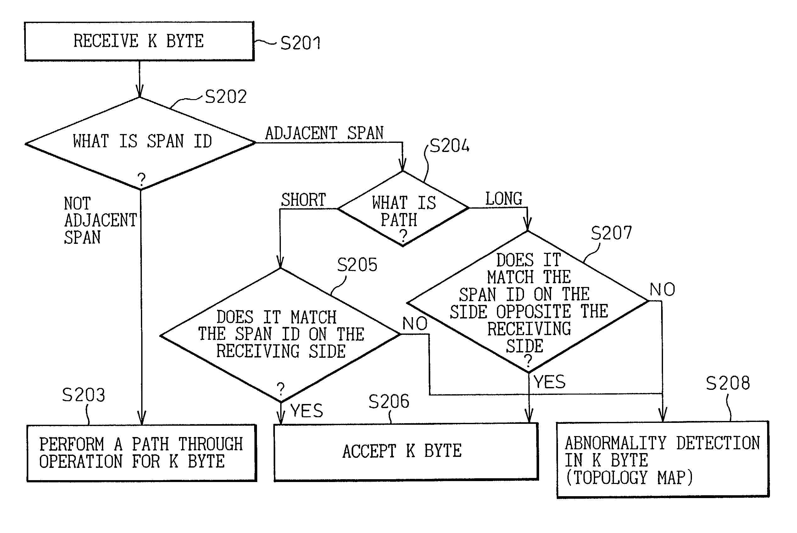
[0045]FIG. 5 shows an example of a BLSR ring system which assigns span IDs according to the present invention.

[0046]In the present invention, in place of node IDs set for each of prior art nodes, span IDs are assigned for each of spans between adjacent nodes. In the example of FIG. 5, the span ID between node 41 and node 48 is “1”, and the span ID between node 42 and node 41 is “2”.

[0047]The span itself is merely the space connecting nodes, and it is possible, in the case of a ring structure, to create a one-to-one correspondence between spans and nodes. For example, in the example of FIG. 5 the number of spans and the number of nodes are both eight. Further, in the present example it is specified such that “the span ID of a span on the ring is assigned to the node of the east side of the corresponding span”. For example, node 41 having the pseudo-node ID “a” corresponds to the span ID “1”, and similarly node 42 having the node ID “b” corresponds to the span ID “2”.

[0048]FIGS. 6A an...


PUM


Abstract

The present invention relates to a ring system, in particular to a ring control node which increases the upper limit of the number of nodes that can be arranged on one ring by a BLSR control and conforms to an increase in line capacity and the scale of a system. The ring control node made of a plurality of nodes for performing ring control, and spans for connecting the plurality of nodes in a ring shape, and each of the nodes detects a fault occurring in a span between itself and another node adjacent thereto, and transmits the fault information to the other node using, as a destination, a span ID assigned to the span.

Description

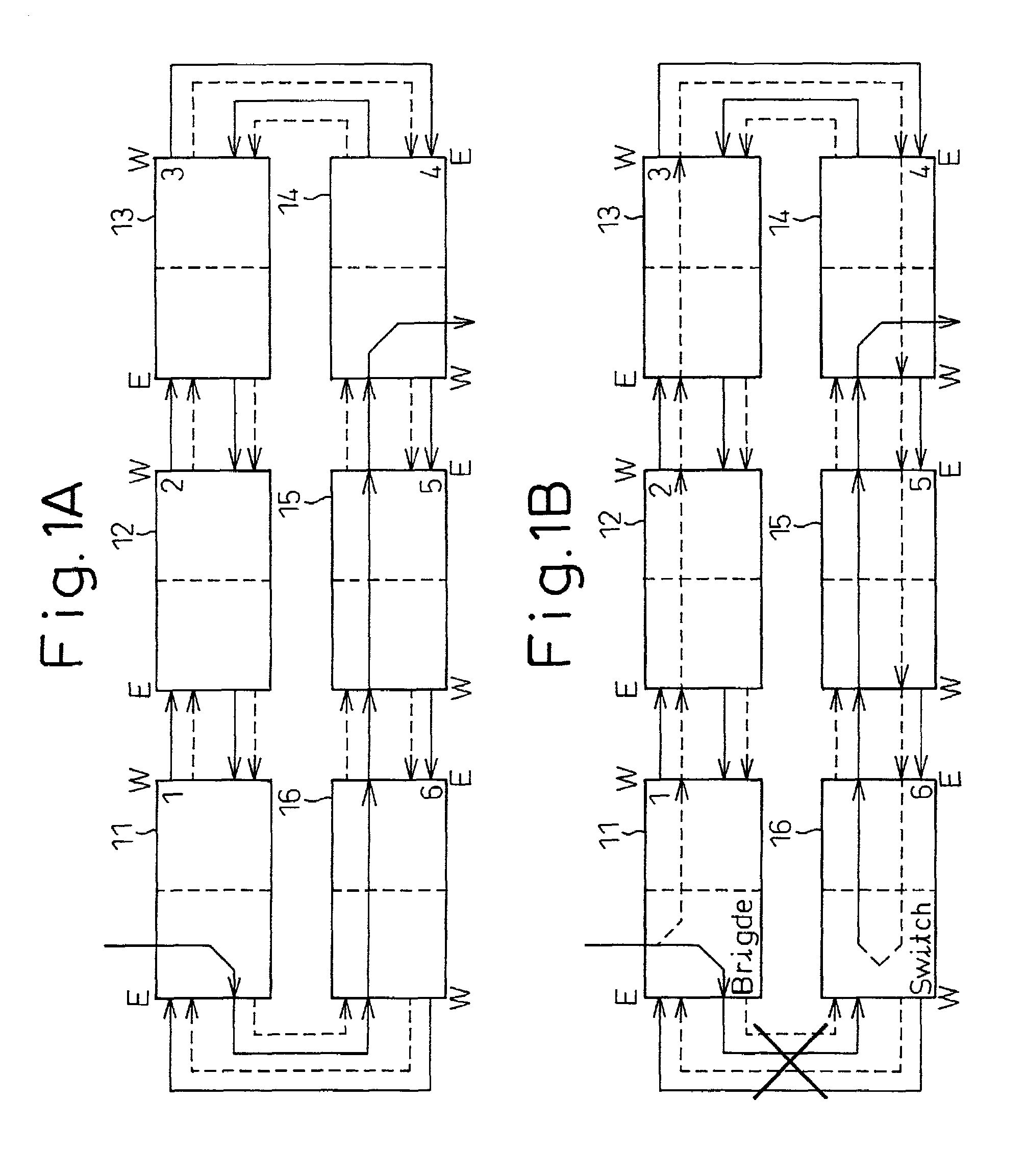
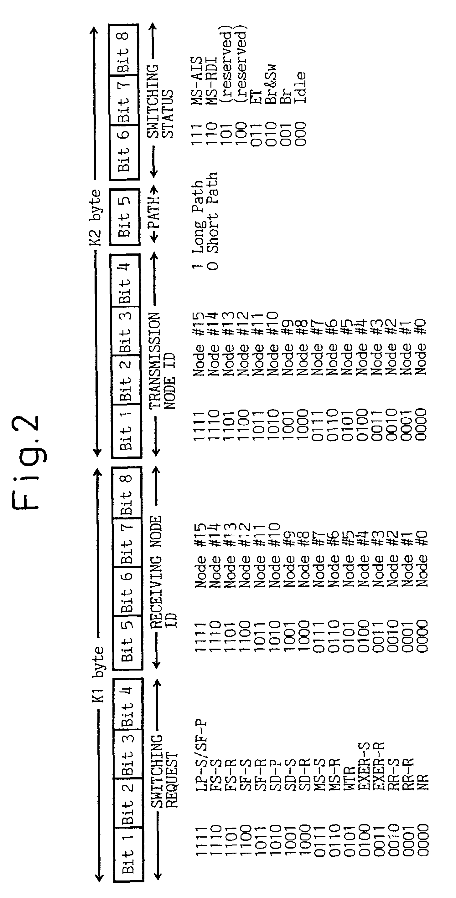
BACKGROUND OF THE INVENTION[0001]1. Field of the Invention[0002]The present invention relates to a ring system and, in particular, to a ring control node which increases the upper limit of the number of nodes that can be arranged on one ring in a BLSR (Bi-directional Line Switched Ring) system utilizing optical transmission devices (nodes), and conforms to the increase in line capacity and the scale of systems accompanying recent technical innovations.[0003]2. Description of the Related Art[0004]The BLSR control method in a ring system is based on the North American standard SONET (Synchronous Optical Network: standard GR-1230-CORE). In a duplex ring line within a BLSR ring system, only a single directional ring is normally used to perform data transfer from a transmitting node to a receiving node. On the other hand, if a fault occurs within the line, data continues to be transferred by switching to the undamaged ring in the opposite direction.[0005]FIGS. 1A and 1B show examples of ...

Claims


Application Information

Patent Timeline
IPC IPC(8): G06F11/00H04L12/24H04L12/437
CPCH04L41/00H04L12/24
Inventor OOKAWA, NAOKATSUOKAMOTO, TAKUYAHONDA, TAKASHI
Owner FUJITSU LTD
Why Eureka
Try Eureka