Bone transmission earphone

a transmission earphone and bone technology, applied in the direction of electrical transducers, contact microphone transducers, loudspeakers, etc., can solve the problems of difficult water-proof or dust-proof construction, pain, uncomfortable feeling of someone, etc., and achieve excellent operability and wearability.

Active Publication Date: 2014-11-27
TEMCO JAPAN
View PDF2 Cites 15 Cited by
  • Summary
  • Abstract
  • Description
  • Claims
  • Application Information

AI Technical Summary

Benefits of technology

[0016]The bone conduction earphone in accordance with the present invention is configured as above, offering advantages that, as a speaker and a microphone, those of bone conduction type are used, and there exists no opening communicating with the outside, whereby the bone conduction earphone can be a unit of a complete waterproof and dustproof construction, and that the earphone structure allows the bone conduction speaker and the bone conduction microphone to be accommodated in the same case, whereby excellent operability and wearability are provided.

Problems solved by technology

However, with this type of speaker and microphone containing type unit, the sound emitting port is opened, and thus it is difficult to provide a water-proof or dust-proof construction.
However, with this bone conduction earphone, the voice of the user is picked up by the bone conduction microphone as a bone-conducted sound through the rigid earmold which is inserted into the external ear canal, being tightly contacted with the wall thereof, and therefore, it is undeniable that someone can have an uncomfortable feeling (or a painful feeling).
As described above, with the aforementioned conventional bone conduction earphone, the voice of the user is picked up by the bone conduction microphone as a bone-conducted sound through the rigid earmold which is inserted into the external ear canal, being tightly contacted with the wall thereof, thereby problems having been presented that someone can have an uncomfortable feeling (or a painful feeling), that, with this bone conduction earphone, a bone-conducted sound is sensed by the rigid earmold portion, the bone-conducted sound being transmitted directly from the earmold to the bone conduction microphone, with no consideration being given about the control of the acoustical characteristics (frequency characteristics) in that portion, and further that no special water-proof measure is taken.

Method used


Image

  • Bone transmission earphone
  • Bone transmission earphone
  • Bone transmission earphone

Examples


Embodiment Construction

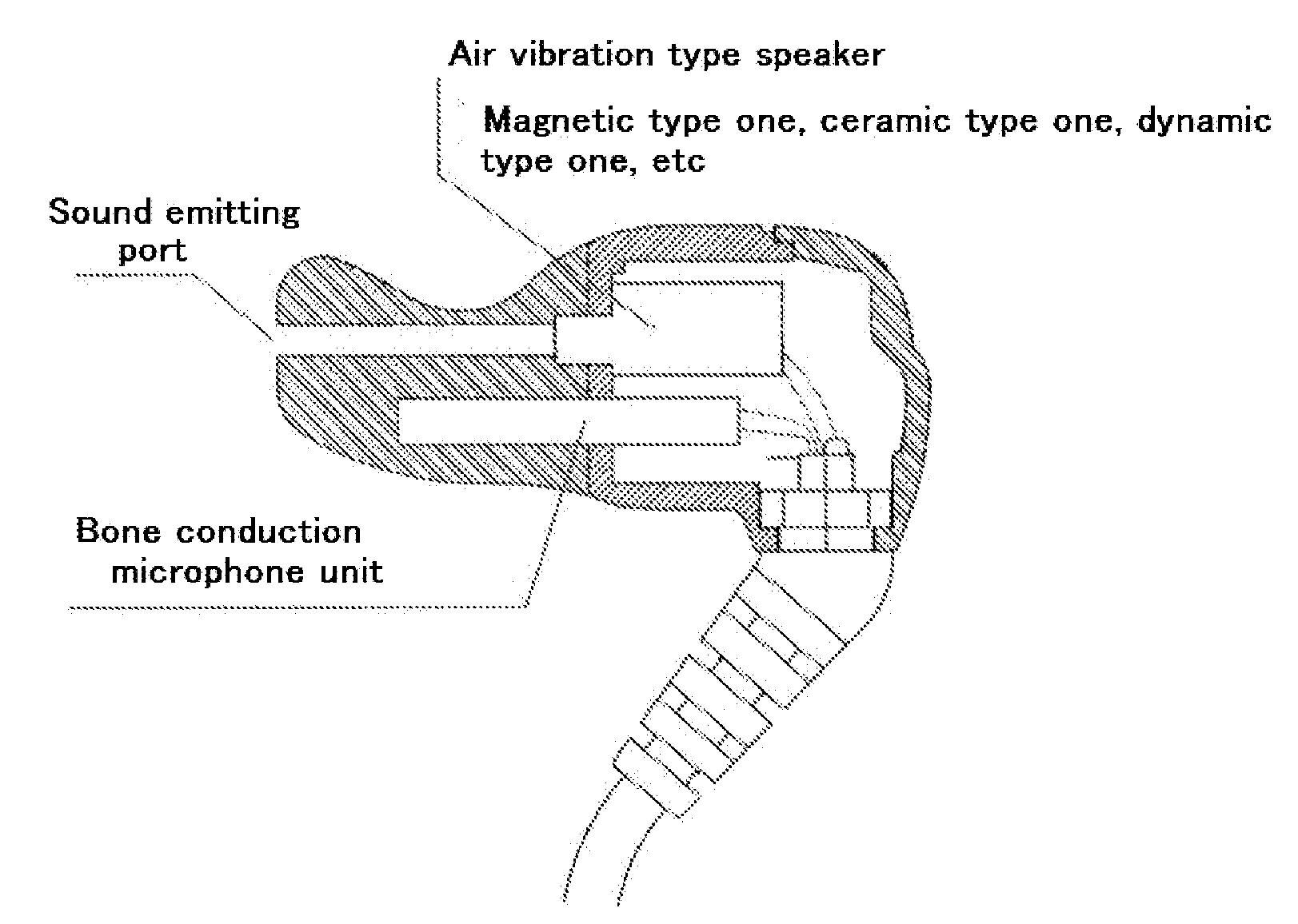
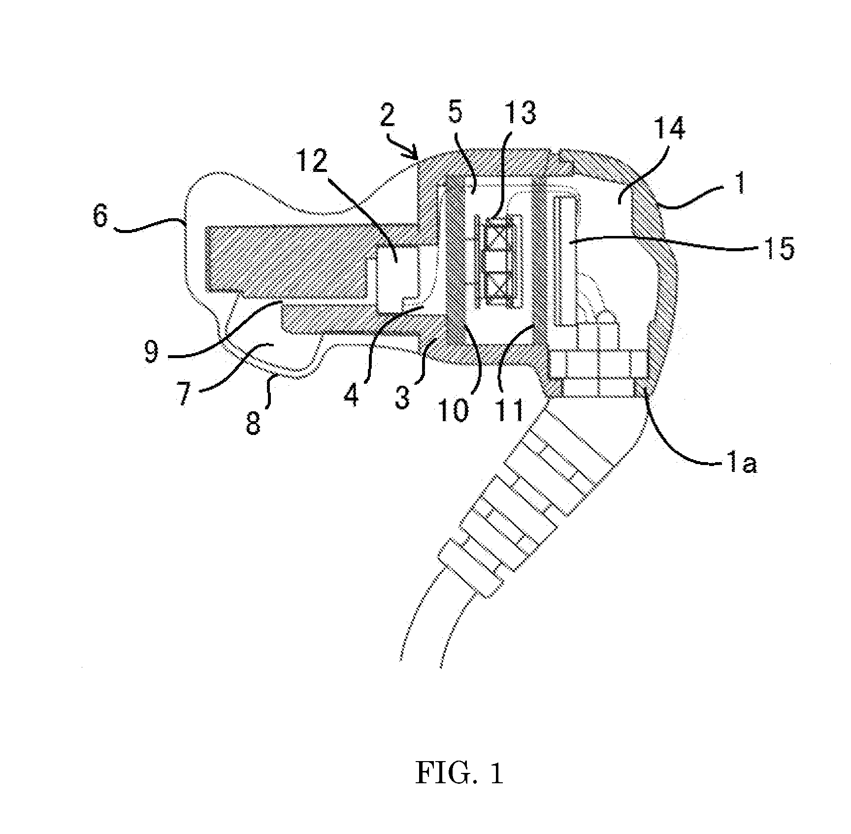
[0021]Hereinbelow, an embodiment for carrying out the present invention will be explained with reference to the accompanying drawings. FIG. 1 is a longitudinal sectional view of one embodiment of a bone conduction earphone in accordance with the present invention, and as shown in that figure, the bone conduction earphone in accordance with the present invention includes a basal end cover 1 having a cable entry opening 1a, and an earphone case 2 which is assembled to the basal end cover 1, accommodating a bone conduction microphone 12 and a bone conduction speaker 13.

[0022]The earphone case 2 includes an ear plug 3 made of a rigid resin having a microphone accommodating space 4 in which the bone conduction microphone 12 to be disposed on the distal end side is accommodated, and a speaker accommodating space 5 in which the bone conduction speaker 13 to be disposed on the basal end side is accommodated, and a sensing cover 6 made of a material softer than that of the ear plug 3 definin...


PUM


Abstract

A basal end cover having a cable entry portion, and an earphone case which accommodates a bone conduction microphone and a bone conduction speaker, being assembled to the basal end cover, with the earphone case including a rigid resin ear plug having a microphone accommodating space in which the bone conduction microphone to be disposed on the distal end side is accommodated, and a speaker accommodating space in which the bone conduction speaker to be disposed on the basal end side is accommodated, and a sensing cover formed of a material softer than that of the ear plug defining the microphone accommodating space, and a bone-conducted sound is picked up by the bone conduction microphone through the sensing cover is provided.

Description

FIELD OF TECHNOLOGY[0001]The following relates to a bone conduction earphone, and more particularly, a bone conduction earphone which incorporates a bone conduction microphone unit and a bone conduction speaker unit in a single casing.BACKGROUND[0002]Up to now, attempts to incorporate a microphone unit and a speaker unit in a single casing have been made. Many of them are those which incorporate, in a single casing, a bone conduction microphone unit as a microphone, and an air vibration type speaker, such as a magnetic type one, ceramic type one, or dynamic type one, as a speaker (see FIG. 3). However, with this type of speaker and microphone containing type unit, the sound emitting port is opened, and thus it is difficult to provide a water-proof or dust-proof construction.[0003]The present applicant has already proposed a bone conduction earphone with which a bone conduction microphone and a bone conduction speaker are incorporated in a single casing (Japanese Unexamined Patent Ap...

Claims


Application Information

Patent Timeline
Patent Type & Authority Applications(United States)
IPC IPC(8): H04R1/46
CPCH04R1/46H04R1/1016H04R2400/00H04R2410/00H04R2460/13H04R1/023H04R25/606
Inventor FUKUDA, MIKIO
Owner TEMCO JAPAN
Why Eureka
Try Eureka