Self-Propelled Ground Milling Machine For Processing Ground Surfaces Having A Milling Device

a self-propelled, ground-mounted technology, applied in electrical control, roads, constructions, etc., can solve the problems of not being able to propulsion the milling device with the milling drum touching the ground, and the driving power should ideally be decreased

Active Publication Date: 2014-11-27
BOMAG
View PDF8 Cites 11 Cited by
  • Summary
  • Abstract
  • Description
  • Claims
  • Application Information

AI Technical Summary

Benefits of technology

[0007]This self-propelled ground milling machine incorporating a milling device has the advantage that rapid switching between operating phase and maneuvering phase is possible when milling ground surfaces, with the result, for example, that a road surface can be milled quickly along adjacent strips having the width of a milling tool. The advantages of the present invention become most apparent when fine milling is carried out, during which the milling drum operates at a particularly high speed, with the result that the present invention is particularly suitable for use in road milling machines. The present invention can, however, fundamentally also be utilized in ground milling machines designed as recyclers and / or stabilizers. The force flow between the drive device and milling device is, according to the present invention, not broken in any of the operational phases or separately reduced. Instead, the driving power of the drive device is reduced, that is to say, control intervention occurs directly at the drive device, more particularly, by appropriately controlling the engine control unit by means of the ground milling machine control unit. This can specifically take place, for example, by regulating the fuel injection rate, which is accordingly reduced for the purpose of reducing the driving power of the drive device and vice versa. In all, according to the present invention, the driving power of the drive device is restricted or, more particularly, its output power is restricted in such a way, that it is essentially limited to at least the traveling performance required for the maneuvering operation. The drive device needs to apply only that driving power that is absolutely necessary for rapid operation, both in the maneuvering phase and in the operating phase, or, more specifically, according to whether the milling device is in the working position or in the maneuvering position.

Problems solved by technology

At the same time, however, the driving power should ideally be decreased to a point at which propulsion of the milling device with the milling drum touching the ground is no longer possible, as would result, for example, in a combustion engine shutdown.

Method used


Image

  • Self-Propelled Ground Milling Machine For Processing Ground Surfaces Having A Milling Device
  • Self-Propelled Ground Milling Machine For Processing Ground Surfaces Having A Milling Device
  • Self-Propelled Ground Milling Machine For Processing Ground Surfaces Having A Milling Device

Examples


Embodiment Construction

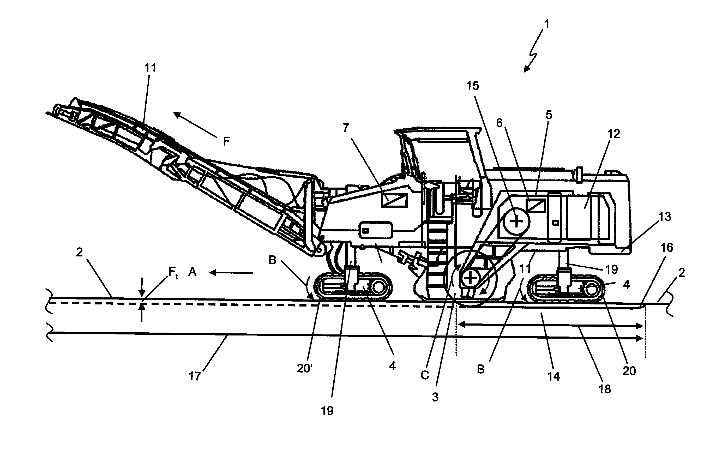
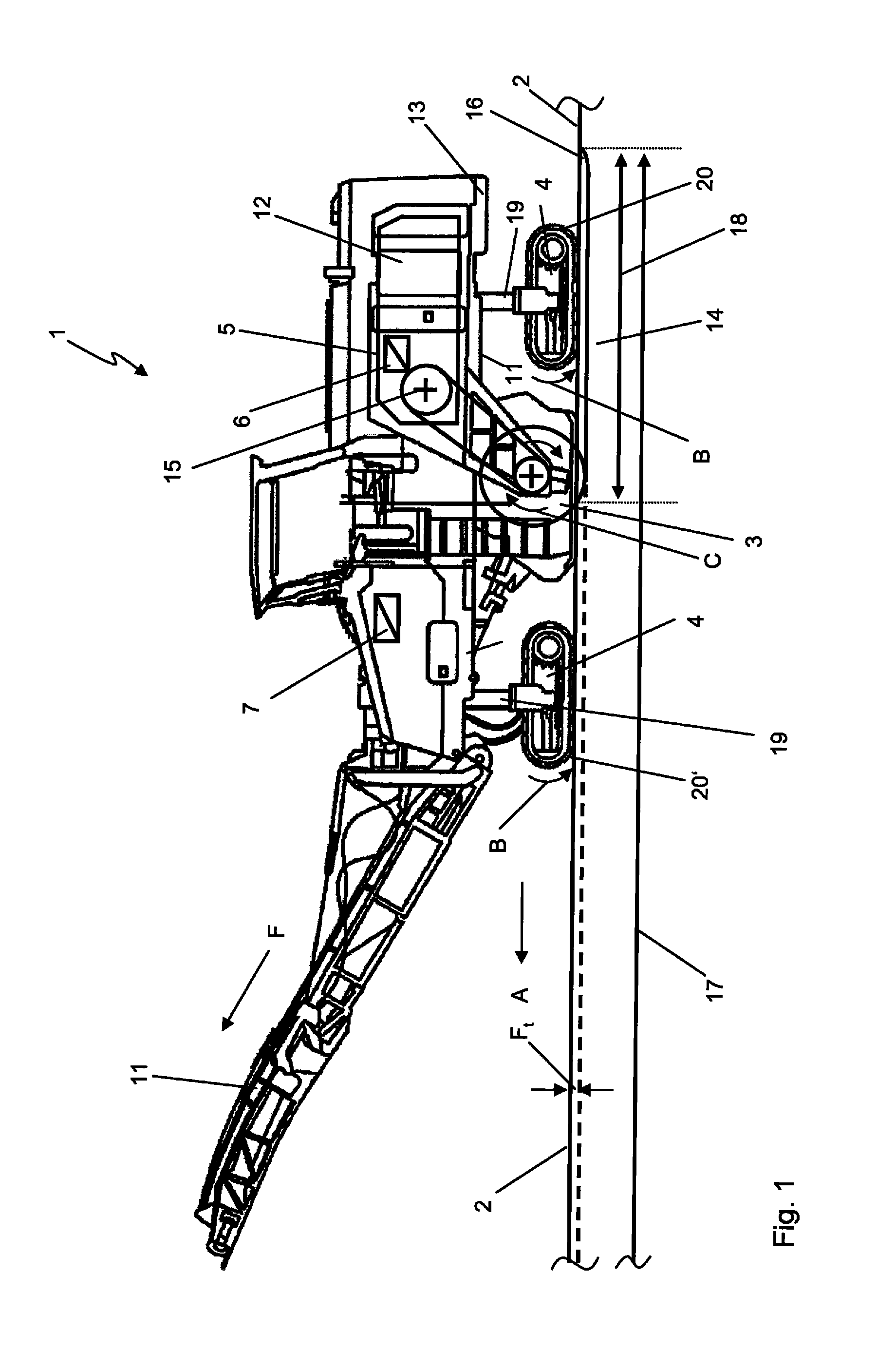
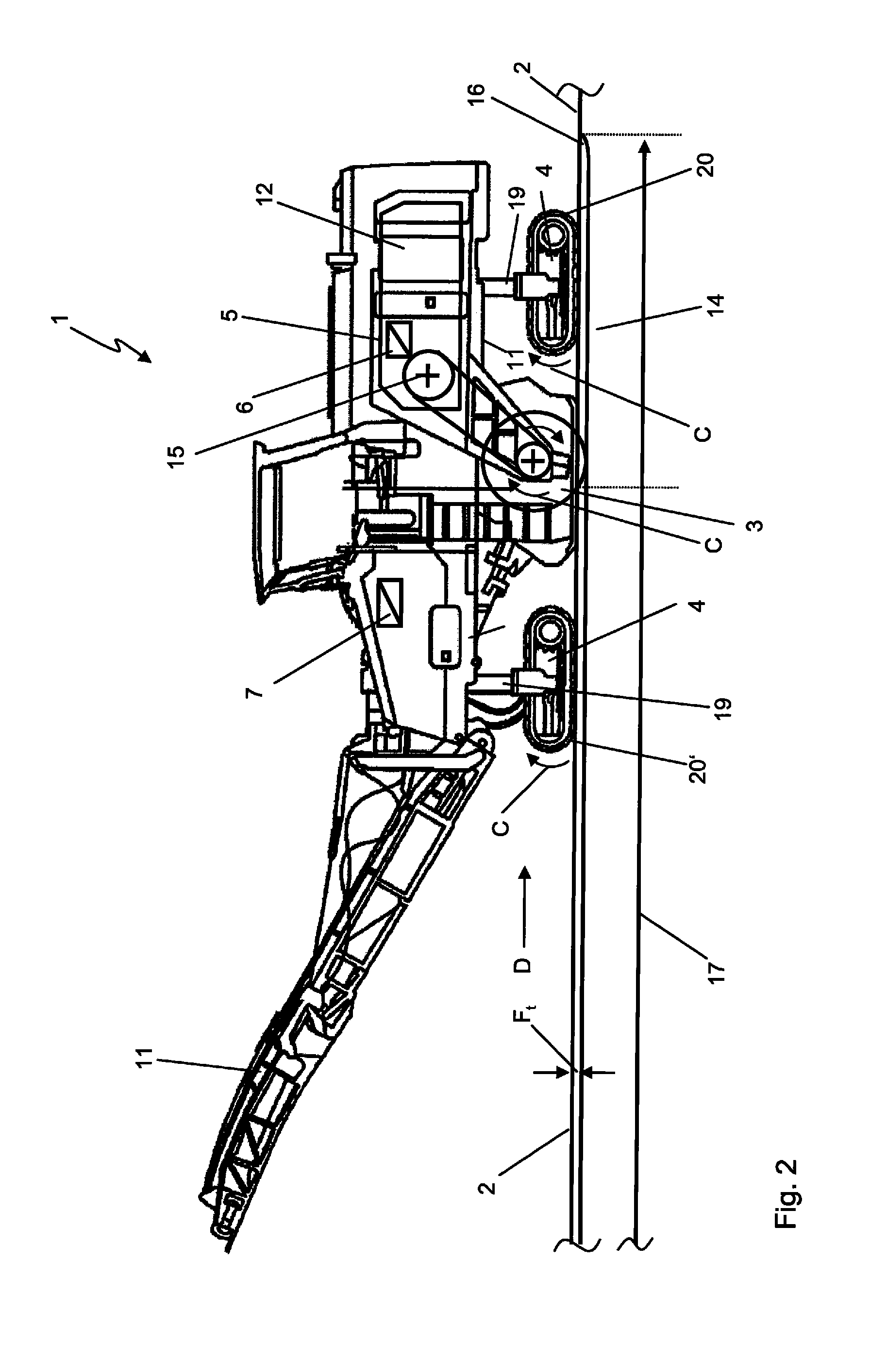
[0031]FIG. 1 is a diagrammatic view of a self-propelled ground milling machine 1 for the treatment of ground surfaces 2 by means of a milling device 3 during an operational phase. During such an operational phase, the ground milling machine 1 is moved in the direction of the arrow A with the aid of transportation means 4, while the milling device 3 comprising a rotating milling tool 9 is set in a working position, in which the milling tool 9 removes material from the ground surface 2 down to a milled surface 14, the milling depth Ft being adjustable. For the purpose of adjusting the milling depth Ft, the milling tool 9 of the milling device 3 is mounted on a ground milling machine frame 13 for pivotal movement about, say, a drive axis 15 of a drive shaft, or, as shown in the present exemplary embodiment, is vertically adjustable by means of lifting columns 19 connecting the frame to the individual crawler tracks of the transportation means 4.

[0032]In this embodiment of the present i...


PUM


Abstract

The present invention relates to a self-propelled ground milling machine for treatment of ground surfaces by means of a milling device, a transportation means and a drive device for driving the transportation means and the milling device. The milling device is mounted on a ground milling machine frame and can be switched between a working position, in which the milling device is in operative contact with the ground surface and a maneuvering position, in which the milling device is not in operative contact with the ground surface. The drive device comprises a drive control unit, which controls the driving power of the drive device. The ground milling machine further comprises a ground milling machine control unit. The ground milling machine control unit controls the interaction of the drive device, the transportation means, and the milling device such that the driving power of the drive device in the maneuvering position of the milling device is automatically caused to be lower than the driving power of the drive device in the working position of the milling device while at least sufficient driving power for the transportation means is maintained.

Description

CROSS-REFERENCE TO RELATED APPLICATIONS[0001]The present application claims priority under 35 U.S.C. §119 of German Patent Application No. 10 2013 008 939.5, filed May 24, 2013, the disclosure of which is hereby incorporated herein by reference in its entirety.FIELD OF THE INVENTION[0002]The present invention relates to a self-propelled ground milling machine for processing ground surfaces. A generic ground milling machine comprises a transportation means, a milling device, and a drive device for the propulsion of the transportation means and the milling device. The milling device is directly or indirectly mounted on a chassis of the ground milling machine and can be switched between a working position, in which the milling device is in operative contact with the ground surface, and a maneuvering position, in which the milling device is not in operative contact with the ground surface. The maneuvering position is necessary, for example, when maneuvering of the ground milling machine...

Claims


Application Information

Patent Timeline
Patent Type & Authority Applications(United States)
IPC IPC(8): E01C23/088
CPCE01C23/088F02D41/021F02D41/12F02D2200/1002F02D2200/1004F02D2200/101F02D2400/12F02D29/02
Inventor NACKE, ANDREASHOFFMANN, ANDRELOEW, TIMOREUTER, MARCO
Owner BOMAG
Why Eureka
Try Eureka