Interference mitigation for multiple inductive systems

a technology of inductive system and interference mitigation, applied in the direction of electric locking circuit, charging station, transportation and packaging, etc., can solve the problems of reducing the efficiency of one or both systems, interrupting operation, and interfering with one another, so as to reduce interference, reduce interference, and reduce interference.

Active Publication Date: 2014-11-27
PHILIPS IP VENTURES BV
View PDF5 Cites 53 Cited by
  • Summary
  • Abstract
  • Description
  • Claims
  • Application Information

AI Technical Summary

Benefits of technology

[0005]In one aspect, interference is mitigated between multiple inductive sub-systems by altering operation of one or both sub-systems. In one embodiment, in response to an interference causing event, one or more of the inductive sub-systems temporarily adjusts operation to reduce interference. In another embodiment, a controller receives communication from multiple sub-systems, analyzes the communication, and determines how to instruct the sub-systems to operate so as to reduce interference. In yet another embodiment, multiple inductive sub-systems can coordinate to operate out of phase with respect to one another to reduce interference. In another embodiment, where one of the sub-systems is a data transfer inductive sub-system, communication from the data transfer inductive sub-system can be mimicked by the other inductive sub-system so that both sub-systems transmit the communication.
[0006]In another aspect, interference between multiple inductive sub-systems can be mitigated by specific physical positioning of the transmitters of the inductive sub-systems. In one embodiment, the transmitter for the first inductive sub-system and the transmitter for the second inductive sub-system are oriented approximately orthogonal to one another in order to reduce interference between them.

Problems solved by technology

Inductive systems that operate in close proximity can cause interference with one another.
This interference can decrease efficiency in one or both systems.
In some circumstances the interference can interrupt operation, interrupt communication, or cause other malfunctions.
Accordingly, even if interference does not significantly effect charging rate, frequent vibration or noise from a portable electrical device can annoy a user and discourage the use of simultaneous use of inductive power supply systems.

Method used


Image

  • Interference mitigation for multiple inductive systems
  • Interference mitigation for multiple inductive systems
  • Interference mitigation for multiple inductive systems

Examples


Embodiment Construction

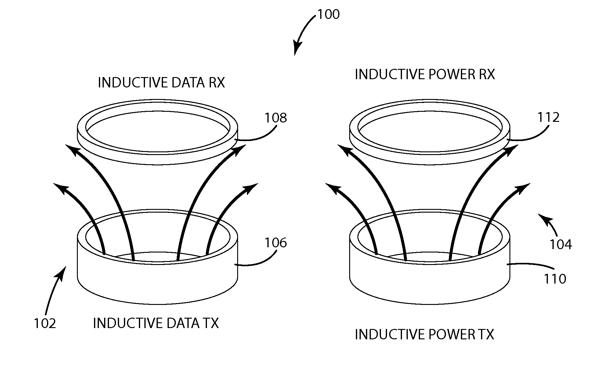
[0025]Interference can arise when multiple inductive systems operate in close proximity at the same time. For example, a modern automobile can integrate an inductive charging unit and a wireless communication system. The inductive charging unit can be used to inductively charge an automobile user's portable electronic devices and the wireless communication system can be used to perform a variety of vehicle functions, such as unlocking vehicle doors when a wireless key fob is present or enabling a vehicle power switch when the wireless key fob is present.

[0026]FIG. 1 illustrates a system 100 that includes an inductive data sub-system 102 and an inductive power sub-system 104 where interference can arise. In one embodiment, the inductive data sub-system 102 can be a wireless key fob system and the inductive power sub-system 104 can be an inductive charging unit for wirelessly charging portable devices, such as cell phones. In alternative embodiments, both sub-systems could be inductiv...


PUM


Abstract

A system and method for mitigating interference between two or more inductive systems. Interference can be mitigated by, in response to an interference causing event, temporarily adjusting operation of one or more of the inductive sub-systems to reduce interference. A controller can receives communication from multiple inductive systems and instruct the systems to operate so as to reduce interference. The inductive systems can coordinate to operate out of phase with respect to one another to reduce interference. Communication from a data transfer inductive system can be mimicked by another inductive system so that both systems transmit the communication. Interference between multiple inductive systems can be mitigated by specific physical positioning of the transmitters of the inductive sub-systems.

Description

BACKGROUND OF THE INVENTION[0001]The present invention relates to reducing or preventing interference between two or more inductive systems.[0002]Inductive systems that operate in close proximity can cause interference with one another. This interference can decrease efficiency in one or both systems. In some circumstances the interference can interrupt operation, interrupt communication, or cause other malfunctions. Inductive systems are commonly used for both data transfer and power transfer.[0003]Many portable devices are programmed to vibrate or make sound when charging is interrupted. Accordingly, even if interference does not significantly effect charging rate, frequent vibration or noise from a portable electrical device can annoy a user and discourage the use of simultaneous use of inductive power supply systems.SUMMARY OF THE INVENTION[0004]A variety of systems and methods for mitigating interference between two or more inductive systems are provided.[0005]In one aspect, in...

Claims


Application Information

Patent Timeline
Patent Type & Authority Applications(United States)
IPC IPC(8): H04B5/00
CPCH04B5/0087H04B5/0037H04B5/0031H04B5/0043H04B5/0056E05B2047/0061E05B2047/0063B60L2250/12B60L2270/147E05B81/88Y02T90/16Y02T90/14B60L53/34B60L53/305B60L53/126H02J50/10H02J7/00034H02J50/40Y02T10/7072Y02T90/12Y02T10/70H02J50/80H02J50/12
Inventor MOES, BENJAMIN C.KUYVENHOVEN, NEIL W.NGUYEN, HAI D.SCHWANNECKE, JOSHUA K.LIFF, DALE R.ZUP, ANDREW
Owner PHILIPS IP VENTURES BV
Why Eureka
Try Eureka