Apparatus and method for partial interference alignment in multi-antenna communication system

a communication system and antenna technology, applied in the field of interference alignment technology, can solve the problems of reducing the overall system performance, reducing the number of antennas, and requiring undue computational complexity for calculating precoding, so as to reduce the effect of due, minimize interference, and optimize the effect of performan

Inactive Publication Date: 2014-11-27
ELECTRONICS & TELECOMM RES INST
View PDF12 Cites 17 Cited by
  • Summary
  • Abstract
  • Description
  • Claims
  • Application Information

AI Technical Summary

Benefits of technology

[0023]In accordance with an embodiment of the present invention, it is possible to reduce an effect due to the interference between the networks when performing a partial interference alignment in a multi-antenna communication network, by determining a candidate group to be subjected to an interference alignment in consideration of real-time interference channel information, path loss, ACI (Adjacent Channel Interference) and performing a precoding that minimizes the interferences on the nodes that are not selected as the candidate group and the nodes that are subjected to the interference alignment to transmit/receive signals in a case where the number of antennas are required more than necessary for al

Problems solved by technology

As a result, signal interferences between adjacent cells increase, which in turn leads to the degradation of the overall system performance.
However, interference alignment technology has a disadvantage in that an undue computational complexity is required for calculating precoding/decoding matrixes, which are used in modulation and demodulation stages to perform the interference alignment, and each node should know a large amount of radio channel condition information.
Further, the number of the antennas needs to increase in proportion to the number of interference sources in order to make the aligned interference nul

Method used


Image

  • Apparatus and method for partial interference alignment in multi-antenna communication system
  • Apparatus and method for partial interference alignment in multi-antenna communication system
  • Apparatus and method for partial interference alignment in multi-antenna communication system

Examples


Embodiment Construction

[0030]In the following description of the present invention, if the detailed description of the already known structure and operation may confuse the subject matter of the present invention, the detailed description thereof will be omitted. The following terms are terminologies defined by considering functions in the embodiments of the present invention and may be changed operators intend for the invention and practice. Hence, the terms need to define throughout the description of the present invention.

[0031]Hereinafter, the embodiments of the present invention will be described in detail with reference to the accompanying drawings.

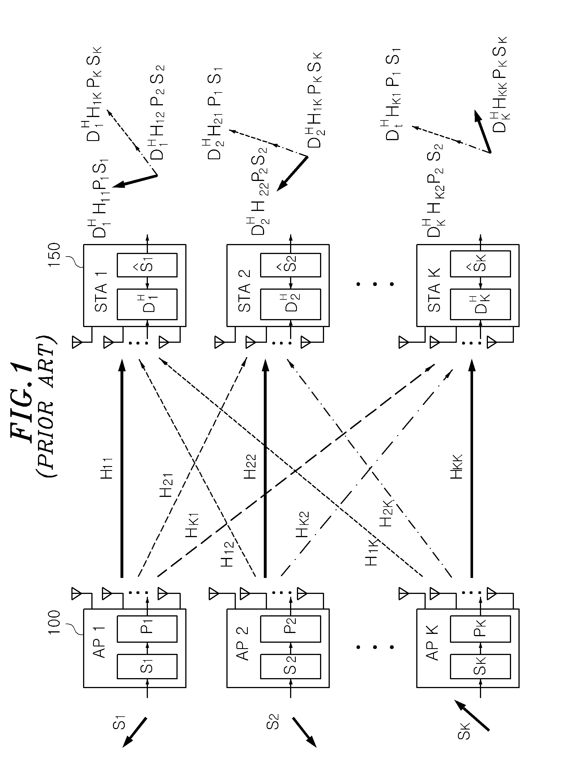
[0032]FIG. 1 shows an illustrative view of interference channels of a K-number of users with a multi-antenna in a wireless environment in accordance with a prior art, which illustrates a situation where a plurality of stations (STAs) 150 having a multi-antenna shares the same channel with a plurality of access points (APs) to communicate with each other t...


PUM


Abstract

A method for a partial interference alignment in a multi-antenna communication system includes, checking the number of access points (APs) operating at the same channel or adjacent channel; and calculating LIPs (Leakage Interference Power) that the respective APs have an effect on each base-station (STA). Further, the method includes choosing the upper three AP-STA pairs having the highest LIP in order as a candidate group for interference alignment; and performing a partial interference alignment on the candidate group for interference alignment.

Description

CROSS-REFERENCE TO RELATED APPLICATION(S)[0001]The present invention claims priority of Korean Patent Application No. 10-2013-0057002, filed on May 21, 2013, which is incorporated herein by reference.FIELD OF THE INVENTION[0002]The present invention relates to an interference alignment technology between networks with a MIMO (Multi Input and Multi Output) technique that are composed of a plurality of base station-terminal pairs. More particularly, the present invention relates to an apparatus and method for a partial interference alignment in a multi-antenna communication network, which is capable of determining a candidate group to be subjected to an interference alignment in consideration of real-time interference channel information, path loss, ACI (Adjacent Channel Interference) and transmitting / receiving signals by performing a precoding that minimizes the interferences on the nodes that are not selected as the candidate group and the nodes that are subjected to the interferenc...

Claims


Application Information

Patent Timeline
IPC IPC(8): H04L25/08
CPCH04L25/08H04L25/03343H04L25/03891H04L2025/03426H04B7/024H04B7/0456H04B15/00
Inventor OH, JINHYUNGKO, GWANGZEENKIM, IGORSONG, MYUNG SUN
Owner ELECTRONICS & TELECOMM RES INST
Why Eureka
Try Eureka