Injection device

Inactive Publication Date: 2014-11-27
HASELMEIER SARL
View PDF2 Cites 8 Cited by
  • Summary
  • Abstract
  • Description
  • Claims
  • Application Information

AI Technical Summary

Benefits of technology

The injection device described in this patent controls the amount of injection fluid that is ejected. It has a control element and a feed part that can be adjusted to set the quantity of injection fluid. The device also has a blocking position that prevents ejecting an excessive amount of fluid. The blocking element prevents movement of the feed part in the direction of the longitudinal center axis in the proximal direction. The injection device is easy to operate with a latching device that acts between the feed part and the housing and a longitudinal guide that prevents the feed part from rotating during the injection operation. The dosing member is connected to the housing and moves along a helical line, which reduces the force required to eject the fluid. The patent aims to provide an improved injection device that is efficient and easy to use.

Problems solved by technology

However, the strength of the latching mechanism influences the torque that the user has to apply in order to turn the operator-controlled knob and set the dose.

Method used


Image

  • Injection device
  • Injection device
  • Injection device

Examples


Embodiment Construction

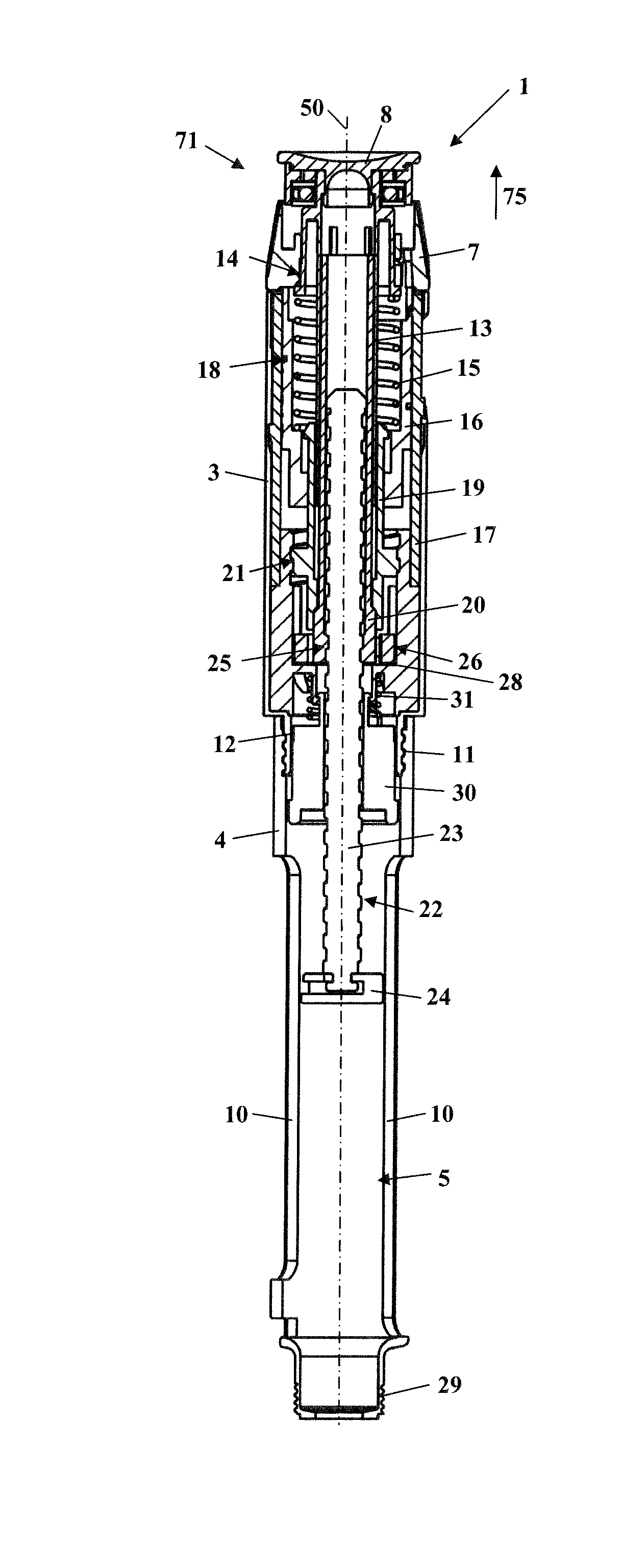
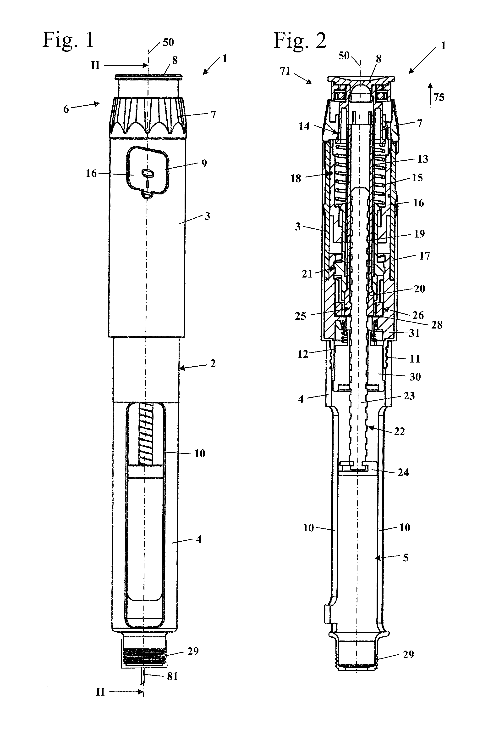
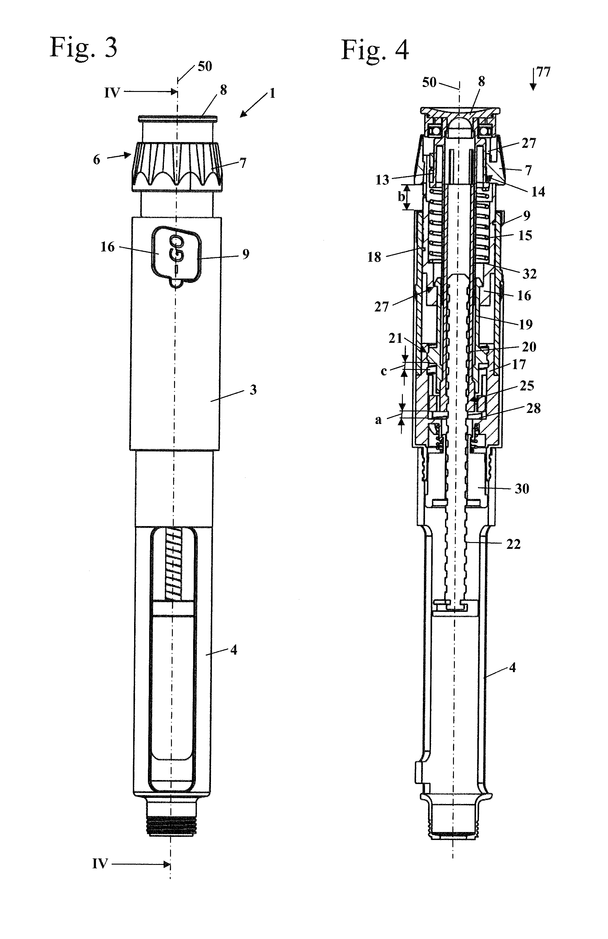
[0044]The injection device 1 shown in FIG. 1 has a housing 2 which includes an upper, distal housing part 3 and a holder 4 which is arranged on the proximal side of the upper housing part 3. At its proximal end, the holder 4 has an external thread 29, to which an injection needle 81, which is shown schematically in FIG. 1, can be screw-connected. A receptacle 5, which is shown in FIG. 2, for a vessel with injection fluid is realized in the holder 4. The vessel with injection fluid is not shown in the figures. As shown in FIG. 1, the holder 4 includes at least one recess 10, through which the vessel with injection fluid can be seen. As a result, the operator can easily recognize whether any injection fluid is still present in the vessel. As shown in FIG. 2, two recesses 10, which are arranged opposite one another, are provided on the holder 4.

[0045]As shown in FIG. 1, an operator-manipulated element 6, which has an adjustment sleeve 7 and an actuating knob 8 which is arranged on the ...


PUM


Abstract

An injection device defines a longitudinal center axis, a proximal direction and a distal direction. The injection device includes a housing having a receptacle for an injection fluid vessel and an operator-manipulated element configured to be rotatable to set an amount of injection fluid to be dispensed. The operator-manipulated element is further configured to move relative to the housing in the direction of the center axis in the distal direction when rotated. The operator-manipulated element further is displaceable in the proximal direction to dispense injection fluid. A feed part is connected to the operator-manipulated element in a rotatably fixed manner and is displaced in the direction of the center axis in the distal direction during the setting of the amount of injection fluid to be dispensed. The feed part is connected to the housing in a rotatably fixed manner and is displaced in the direction of the center axis in the distal direction when the injection fluid is dispensed. A blocking contour extends around the center axis in a spiral-like manner and coacts with the feed part and to block a movement of the feed part in the direction of the center axis in the proximal direction. The blocking contour has at least at one location an interruption configured to allow a movement of the feed part in the direction of the center axis in the proximal direction.

Description

CROSS REFERENCE TO RELATED APPLICATIONS[0001]This application is a continuation application of international patent application PCT / EP2013 / 000358, filed Feb. 6, 2013, designating the United States and claiming priority from German application 20 2012 001 410.2, filed Feb. 10, 2012, and the entire content of both applications is incorporated herein by reference.BACKGROUND OF THE INVENTION[0002]U.S. Pat. No. 8,747,367 makes known an injection device where a turning movement of the control element is converted via two threaded connections into an axial movement of a feed part in the distal direction. To eject the injection fluid from the vessel, the feed part is moved in the axial direction and thus acts on a dosing piston which ejects the injection fluid from the vessel.[0003]In the case of the injection device shown in U.S. Pat. No. 8,747,367, very different quantities of injection fluid can be set. The possible quantities to be set are predetermined via a latching device which is co...

Claims


Application Information

Patent Timeline
IPC IPC(8): A61M5/315
CPCA61M5/31551A61M5/24A61M5/3158A61M5/31535A61M5/31543A61M5/3156
Inventor KEITEL, JOACHIM
Owner HASELMEIER SARL
Why Eureka
Try Eureka