
A device for measuring physical quantities on electrical conductor cables with outer perimetral insulation

Inactive Publication Date: 2018-12-27
RODILLA SALA VICENTE +1
View PDF0 Cites 1 Cited by
  • Summary
  • Abstract
  • Description
  • Claims
  • Application Information

AI Technical Summary

Benefits of technology

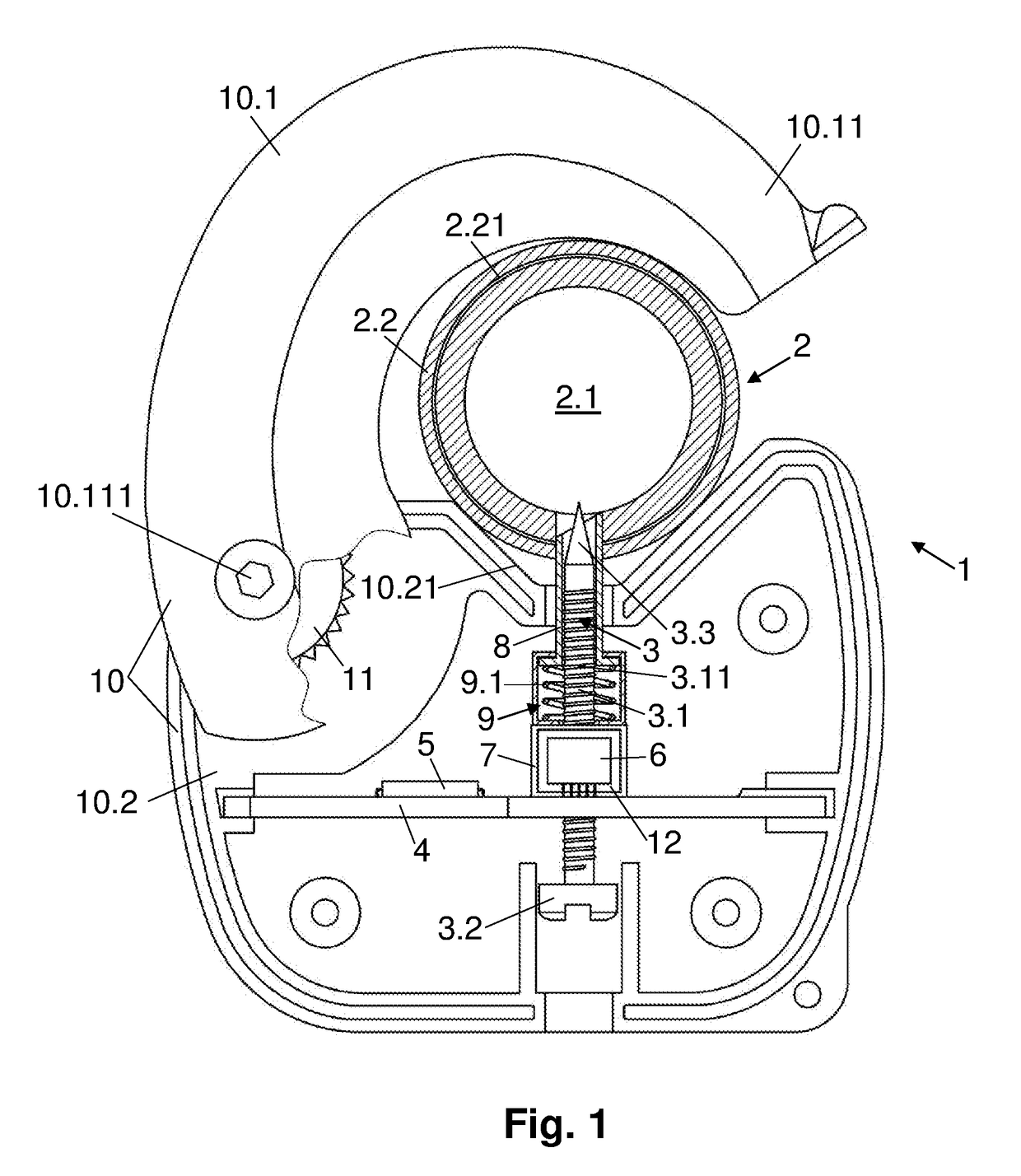
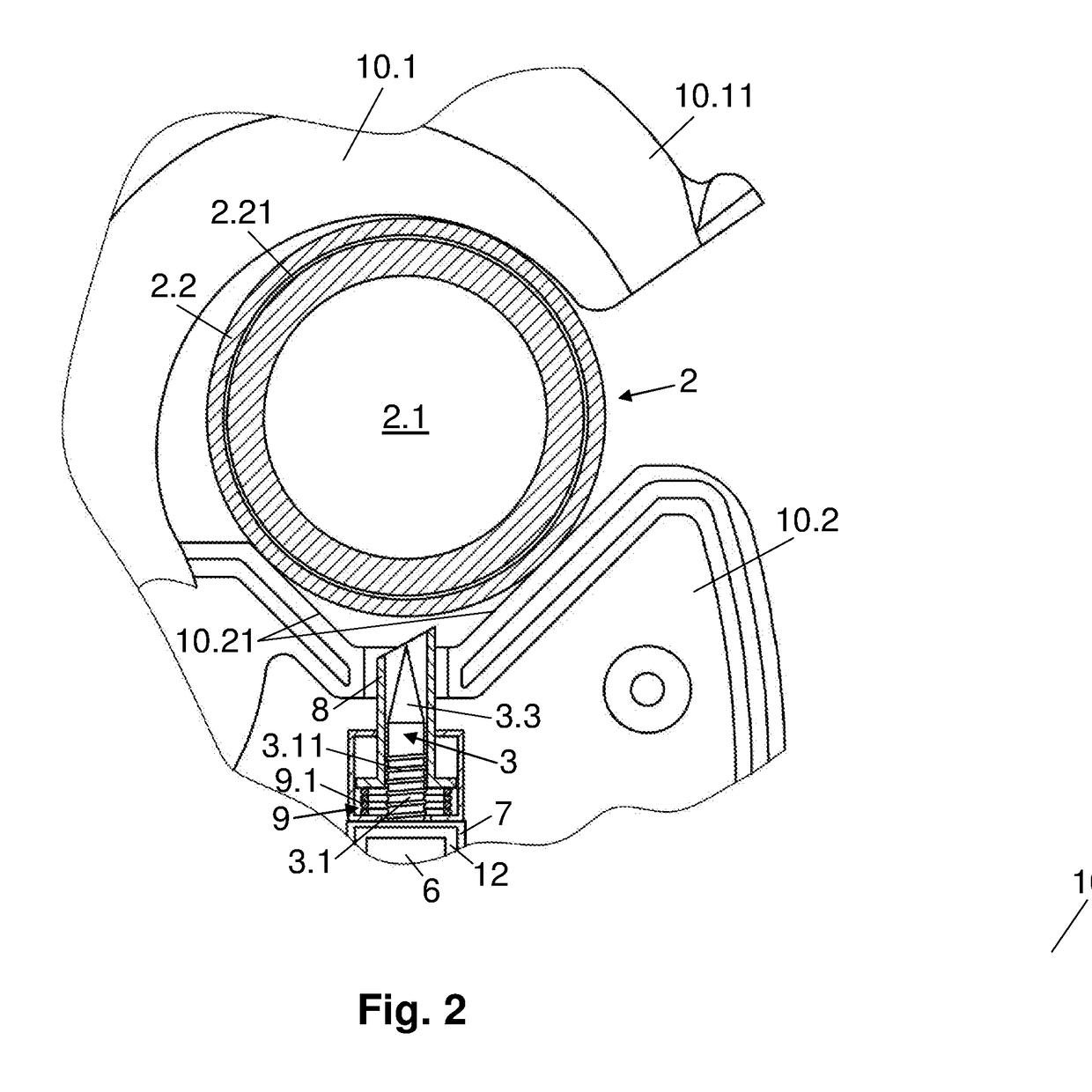
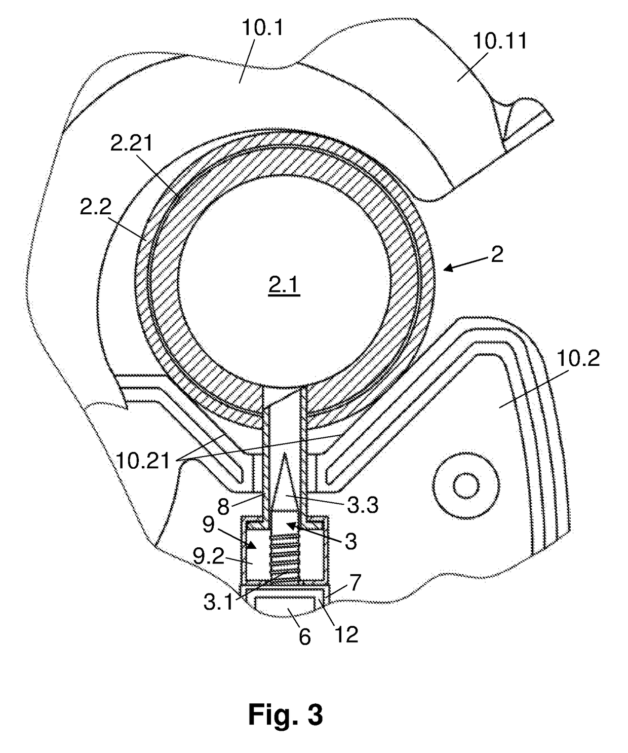
The present invention relates to a device for measuring physical quantities in an electrical conductor cable. The device has a metallic punch that acts as a sensor for multiple physical quantities, such as temperature, vibrations, voltage, etc. The punch is placed outside a support base and pierces the metallic core of the cable, minimizing variations and dissipation between the measured values and the actual conditions inside the cable. The device can also measure other complementary parameters outside the cable, such as magnet field, current, and voltage. A threaded portion on the metallic punch allows for better penetration and adaptation to different insulation thicknesses. An insulated dielectric path or tunnel can prevent short-circuits between the metallic punch and the cable's reinforcement or insulation. The device can be assembled on any electrical conductor cable without interruptions due to disconnection and can safely and permanently operate.

Problems solved by technology

However, these known devices only allow measuring current and voltage in the conductor cable in order to control power consumption at each instant by tampering with the ends of the cables or cutting and peeling their insulation at some point of the wiring.

Method used


Image

  • A device for measuring physical quantities on electrical conductor cables with outer perimetral insulation
  • A device for measuring physical quantities on electrical conductor cables with outer perimetral insulation
  • A device for measuring physical quantities on electrical conductor cables with outer perimetral insulation

Examples


second embodiment

[0025]FIG. 5 is the same as FIG. 4, but showing the metallic punch with a threaded section that threads onto the support base.

first embodiment

[0026]FIG. 6 shows a magnified detail of the piercing tip of the metallic punch shown in any of the previous figures.

[0027]FIG. 7 shows a magnified detail of a second embodiment of the piercing tip of the metallic punch shown in any of FIGS. 1 to 6.

[0028]FIG. 8 shows a block diagram of the remote control system of an electrical installation that includes the physical quantity measuring device of FIG. 1.


PUM


Abstract

A device for measuring physical quantities on electric conductors, comprising a casing suitable for assembly on the outside of the conductor via clamping and fastening means, a metallic punch that can be lodged in the metallic core of the conductor for taking measurements and sensing electronics associated to a printed circuit board wherein the metallic punch passes tightly through a support base, the sensing electronics made up of measuring chips encapsulated with multi-chip modular (MCM) technology being fastened on the outside of said support base. The measuring device is used in a remote control and management system of an electrical installation, to optimize the conditions of safety, consumption, energy efficiency, predictive maintenance and CO2 emissions; all this in industrial facilities, buildings and dwellings.

Description

[0001]This invention lies within the field of tools for electricity installations. Specifically, with a device suited for installation on an electrical conductor cable with outer perimetral insulation, thermoplastic or in other materials, in order to perform measurements of physical quantities on the core of said conductor cable, such as for example temperature, mechanical vibrations, magnetic field, amperage, voltage; among other quantities that allow evaluating both the state of the power grid in real time and to predict states of the power grid that we wish to prevent; such as, for example, inappropriate variations in the temperature of the conductor cable due to excessive current density [A / mm2]; or in power consumption in [kW] of grid load; or in the vibrations caused by bearings in bad condition. All this in order to optimize the energy efficiency of said load in the installation, its predictive maintenance, to be warned of technical alarms, prevent overloads, overconsumption,...

Claims


Application Information

Patent Timeline
IPC IPC(8): H01R4/2404G01R1/067G01R21/133H01R4/42H01R4/64
CPCH01R4/2404G01R1/067G01R21/133H01R4/42H01R4/643H01R4/2408H01R4/24
Inventor RODILLA SALA, VICENTERODILLA VALERO, SANDRA
Owner RODILLA SALA VICENTE
Learn More