Method of operating a microlithographic apparatus

Active Publication Date: 2015-06-18
CARL ZEISS SMT GMBH
View PDF2 Cites 1 Cited by
  • Summary
  • Abstract
  • Description
  • Claims
  • Application Information

AI Technical Summary

Benefits of technology

The invention proposes to deliberately illuminate reflective optical elements to adjust the angular light distribution and light energy on a point on a mask after scan integration. By having significantly varying irradiances on the reflective optical elements, the invention allows for more precise adjustments to the angular light distribution and light energy. Additionally, if the irradiance distribution on the array is varied at least according to a Gauss or super Gauss distribution along the first line, the invention facilitates the optimization process required to find a set of tilt angles that tolerates shifts in the irradiance distribution on the array.

Problems solved by technology

A drawback of this approach is that the flexibility to modify the angular light distribution is restricted.

Method used


Image

  • Method of operating a microlithographic apparatus
  • Method of operating a microlithographic apparatus
  • Method of operating a microlithographic apparatus

Examples


Embodiment Construction

I

General Construction of Projection Exposure Apparatus

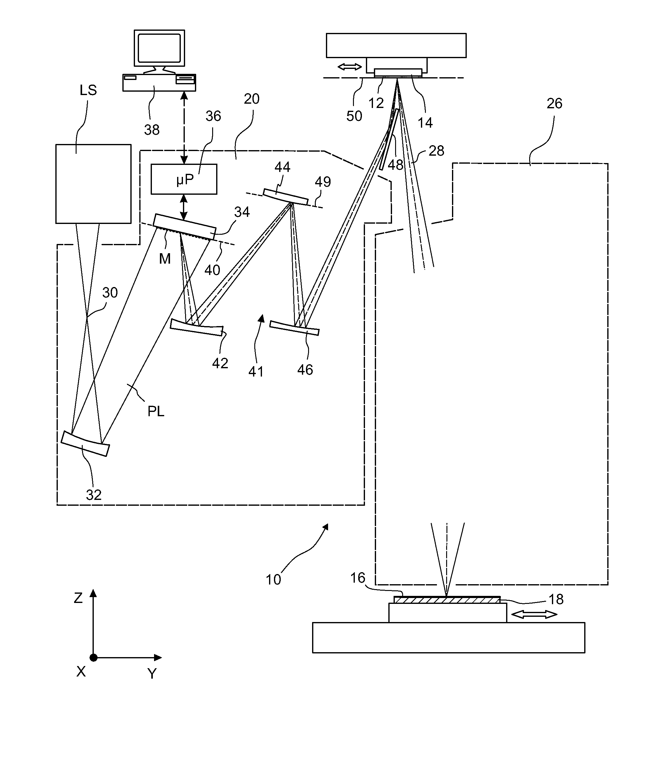
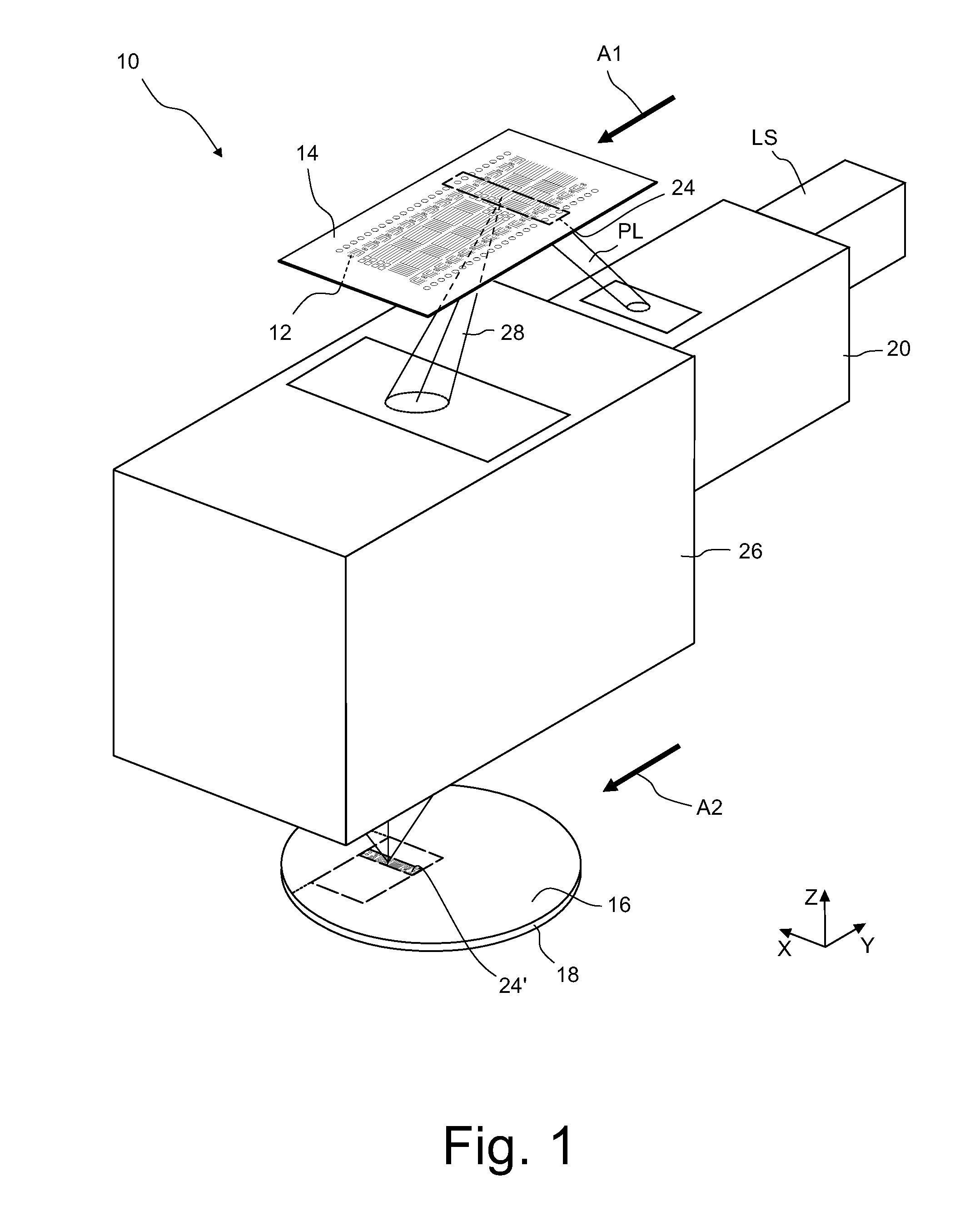
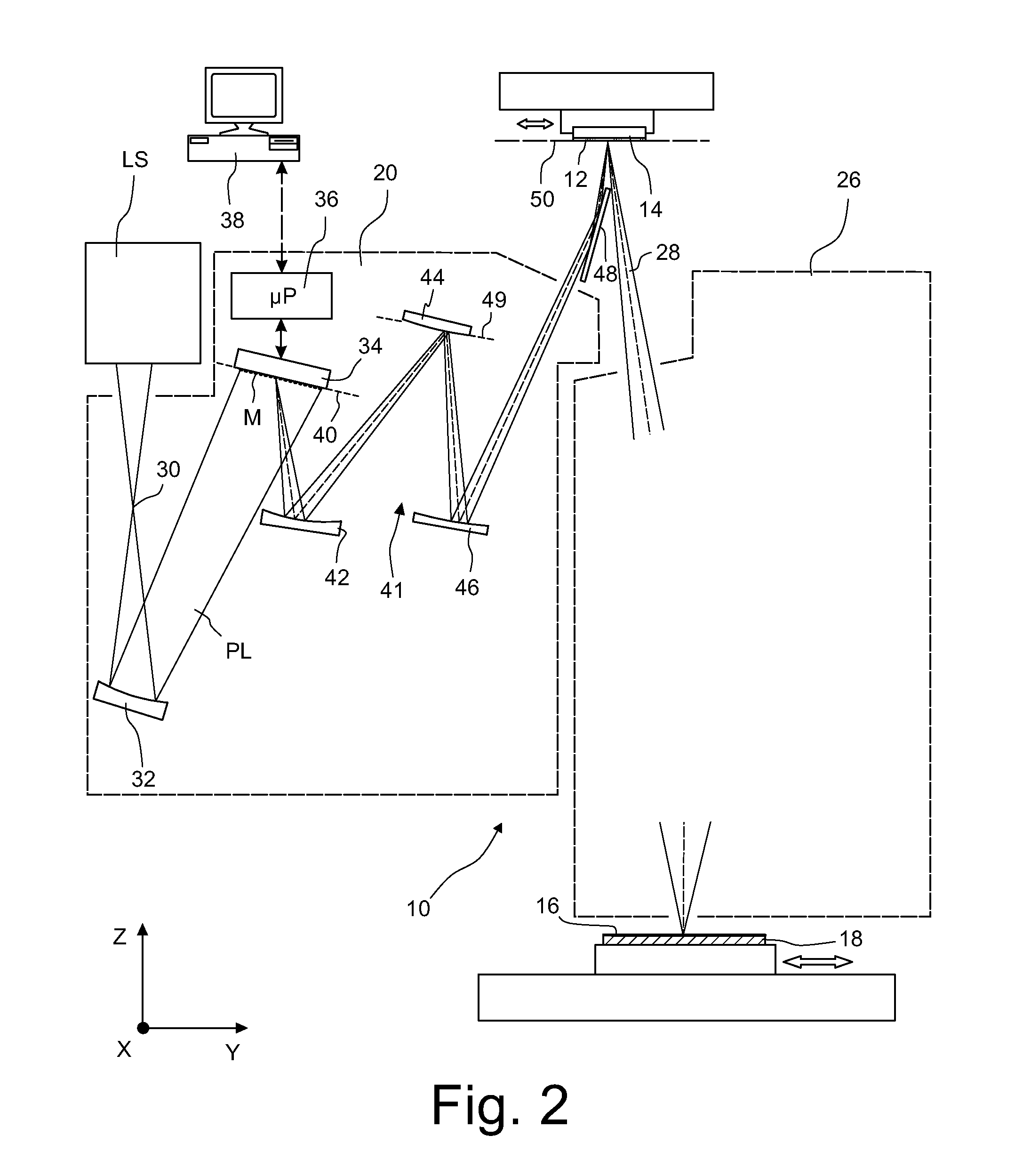
[0083]FIG. 1 is a perspective and highly schematic illustration showing a projection exposure apparatus 10 in accordance with the present invention. The apparatus 10 serves to image a pattern of reflecting structures 12, which are arranged on the underside of a mask 14, on a light-sensitive layer 16 which may be formed, for example, by a photoresist. The light-sensitive layer 16 is supported by a wafer 18 or another suitable substrate which is held by a wafer stage (not shown in FIG. 1).

[0084]The projection exposure apparatus 10 comprises a light source LS that is configured to produce projection light PL having a center wavelength between 5 nm and 30 nm. In the embodiment shown the center wavelength of the projection light PL is approximately 13.5 nm and therefore lies in the extreme ultraviolet spectral range (EUV). Other center wavelengths, in particular between 6.6 nm and 6.8 nm, are also possible.

[0085]In the embodiment show...


PUM


Abstract

A method of operating a microlithographic apparatus comprises the steps of providing an illumination system comprising an array of tiltable mirrors, wherein a light irradiance distribution on the array varies by at least 50% along a first line; specifying a scan integrated target angular light distribution and a target light energy for a point moving through an illumination field along a second line that extends parallel to a scan direction and is an image of the first line; determining a group of those mirrors through which the first line extends; determining tilt angles of the mirrors of the group such that a real angular light distribution and a real light energy for the point approximate the respective target values; producing the illumination field by forming an image of the array on a mask; and imaging a portion of the mask on a surface while the mask moves along the scan direction.

Description

CROSS-REFERENCE TO RELATED APPLICATIONS[0001]The present application is a continuation of, and claims benefit under 35 USC 120 to, international application PCT / EP2012 / 004211, filed Oct. 8, 2012, the entire disclosure of which is incorporated by reference herein.BACKGROUND OF THE INVENTION[0002]1. Field of the Invention[0003]The invention generally relates to a method of operating a microlithographic apparatus, for example a projection exposure apparatus or a mask inspection apparatus. The invention particularly relates to EUV apparatus in which a real image of an array of reflective optical elements is produced on a mask to be imaged. Subject of the invention is also an apparatus which is suitable to perform such a method.[0004]2. Description of Related Art[0005]Microlithography (also referred to as photolithography or simply lithography) is a technology for the fabrication of integrated circuits, liquid crystal displays and other microstructured devices. The process of microlithog...

Claims


Application Information

Patent Timeline
IPC IPC(8): G03F7/20
CPCG03F7/70133G03F7/70558G03F7/70075G03F7/70083G03F7/70091G03F7/70116G03F7/70125G03F7/70358G03F7/704G03F7/7055
Inventor PATRA, MICHAEL
Owner CARL ZEISS SMT GMBH
Why Eureka
Try Eureka