
Method for Service Interface Encoding to Achieve Secure and Robust Network-to-Network Interface

a network-to-network interface and service interface technology, applied in the field of networktonetwork interface service interface encoding methods, can solve the problems of inefficient transport subnetwork resource utilization, memory and computational intensiveness, and inefficien

Active Publication Date: 2014-11-27
INFINERA CORP
View PDF2 Cites 2 Cited by
  • Summary
  • Abstract
  • Description
  • Claims
  • Application Information

AI Technical Summary

Benefits of technology

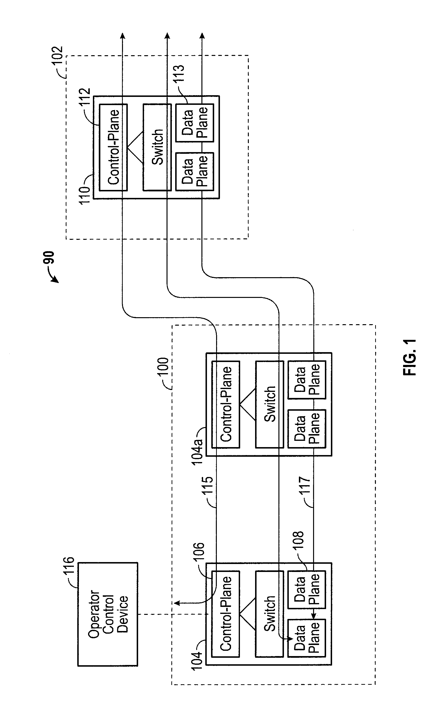
The patent describes a method for determining a path for transmitting data between two nodes in a computer network. The method involves receiving a service request message from an edge node, which includes information about the unique identifiers of the nodes and the requested bandwidth for the transmission. The system then uses this information to determine the path through the network between the ingress port of the first node and the egress port of the second node. The system can also send acknowledgement messages to the edge nodes and access a database to pre-define the path. The technical effect of this invention is to improve the efficiency and reliability of data transmission in computer networks.

Problems solved by technology

Further, service providers prefer to apply a typical router setup sequence to establish all connections in the network, which may cause compatibility issues in some cases, and may optimize for a particular group of customers, and not necessarily for the transport subnetwork as a whole.
Further, edge nodes compute the path locally and typically lack enough information to initiate efficient layer-1 switching, which results in data being sent as IP-over-DWDM (or IP over dumb or statically provisioned pipes), which is inefficient in terms of transport subnetwork resource utilization.
Finally, locally computing the path at the edge nodes requires the core nodes to store and maintain network “states” defined and initiated by the edge nodes, which is memory and computationally intensive and inefficient.

Method used


Image

  • Method for Service Interface Encoding to Achieve Secure and Robust Network-to-Network Interface
  • Method for Service Interface Encoding to Achieve Secure and Robust Network-to-Network Interface
  • Method for Service Interface Encoding to Achieve Secure and Robust Network-to-Network Interface

Examples


Embodiment Construction

[0031]The following detailed description refers to the accompanying drawings. The same reference numbers in different drawings may identify the same or similar elements or features.

[0032]If used throughout the description and the drawings, the following short terms have the following meanings unless otherwise stated:

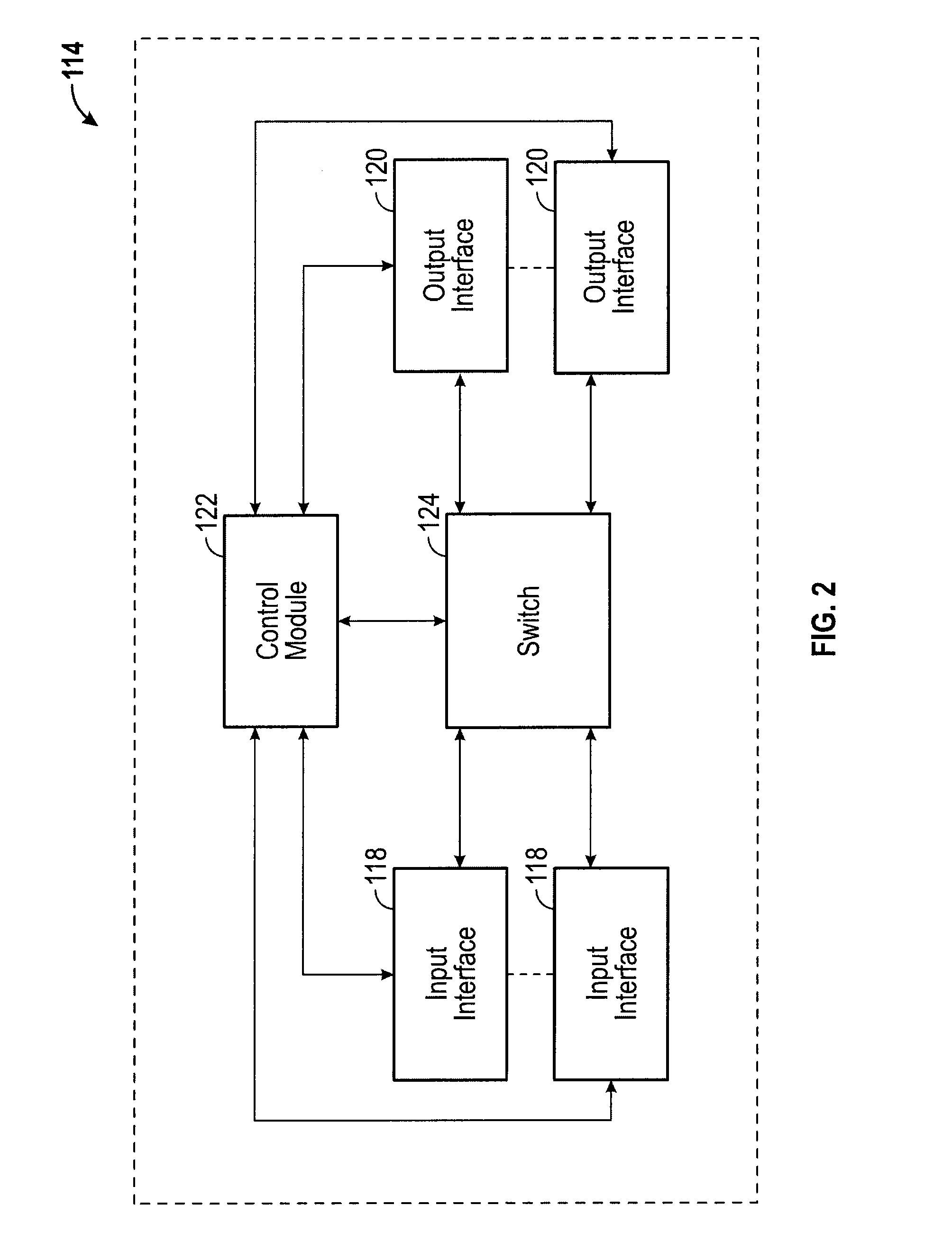
[0033]GMPLS stands for Generalized Multi-Protocol Label Switching, which extends Multi-Protocol Label Switching to encompass time-division (for example, SONET / SDH, PDH, G.709), wavelength (lambdas), and spatial multiplexing (e.g., incoming port or fiber to outgoing port or fiber). The GMPLS framework includes a set of routing protocols which runs on a control module. The Generalized Multiprotocol Label Switching architecture is defined, for example in RFC 3945.

[0034]IETF stands for Internet Engineering Task Force.

[0035]IP stands for Internet Protocol which is a protocol used for communicating data across a packet-switched internetwork using the Internet Protocol Suite, a...


PUM


Abstract

A method includes receiving, by circuitry of a first core node a service request message from an edge node coupled with the first core node. The service request message includes information indicative of: (a) a first unique identifier of an ingress port of the first core node, the first core node being within a transport subnetwork; (b) a second unique identifier of an egress port of a second core node within the transport subnetwork; and (c) a requested transport path bandwidth. The method also includes determining, by the circuitry of the first core node, a transport path through the transport subnetwork between the first core node and the second core node based on the service request, and forming the transport path between the ingress port of the first core node and the egress port of the second core node.

Description

INCORPORATION BY REFERENCE[0001]This application claims priority to the provisional patent application identified by U.S. Ser. No. 61 / 826,954 titled “A method for service interface encoding to achieve secure and robust network-to-network interface,” filed on May 23, 2013, the entire content of which is hereby expressly incorporated herein by reference.FIELD OF THE DISCLOSURE[0002]The disclosure generally relates to service interface encoding methods for network-to-network interfaces, and more particularly to a protocol to facilitate an edge node transmitting a service request message to a core node of a transport subnetwork to set up a transport path on the edge node's behalf. Upon receipt of the service request, the core node sets up the transport path from an incoming node to an outgoing node in the transport subnetwork based on the service request. In one embodiment, the core node processes the service request without transmitting transport subnetwork information to the edge node...

Claims


Application Information

Patent Timeline
Patent Type & Authority Applications(United States)
IPC IPC(8): H04L12/24H04L45/125
CPCH04L41/50H04L45/125
Inventor PAN, PINGSADASIVARAO, AGHINAVA SHIVAKUMARSYED, SHARFUDDINFRENDO, MICHAELLIOU, CHRIS
Owner INFINERA CORP
Learn More