
Control device

a control device and control device technology, applied in the direction of cycle control system, cycle equipment, cycle brakes, etc., can solve the problem and achieve the effect of increasing the size of the attachment member

Active Publication Date: 2014-12-04
SHIMANO INC
View PDF10 Cites 41 Cited by
  • Summary
  • Abstract
  • Description
  • Claims
  • Application Information

AI Technical Summary

Benefits of technology

The patent text describes a control device for a bicycle that can communicate with other equipment or alert the rider with certain information. However, adding a wireless communication unit or notification unit to the attachment member will make it larger. The goal is to provide these features without increasing the size of the attachment member.

Problems solved by technology

However, providing a wireless communication unit or a notification unit in the attachment member will increase the size of the attachment member.

Method used


Image

  • Control device
  • Control device
  • Control device

Examples


Embodiment Construction

[0040]Selected embodiments will now be explained with reference to the drawings. It will be apparent to those skilled in the bicycle field from this disclosure that the following descriptions of the embodiments are provided for illustration only and not for the purpose of limiting the invention as defined by the appended claims and their equivalents.

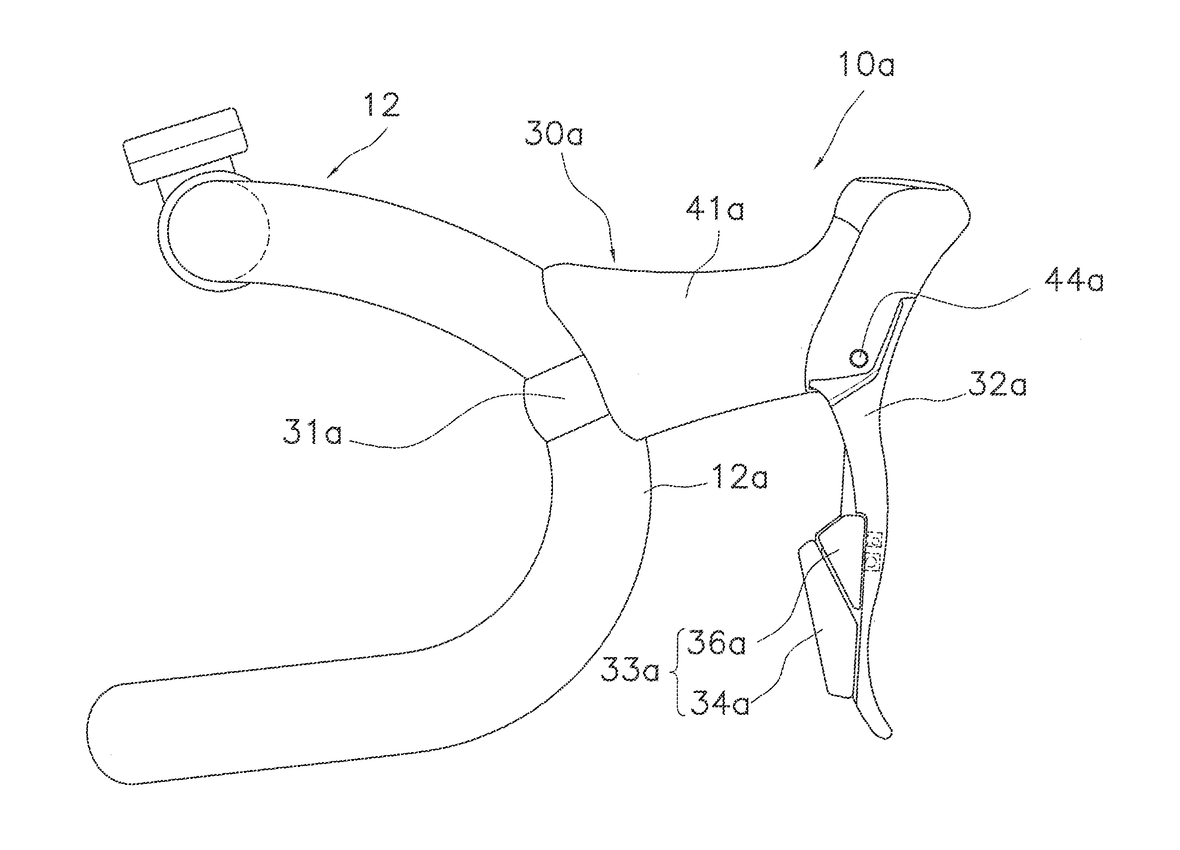
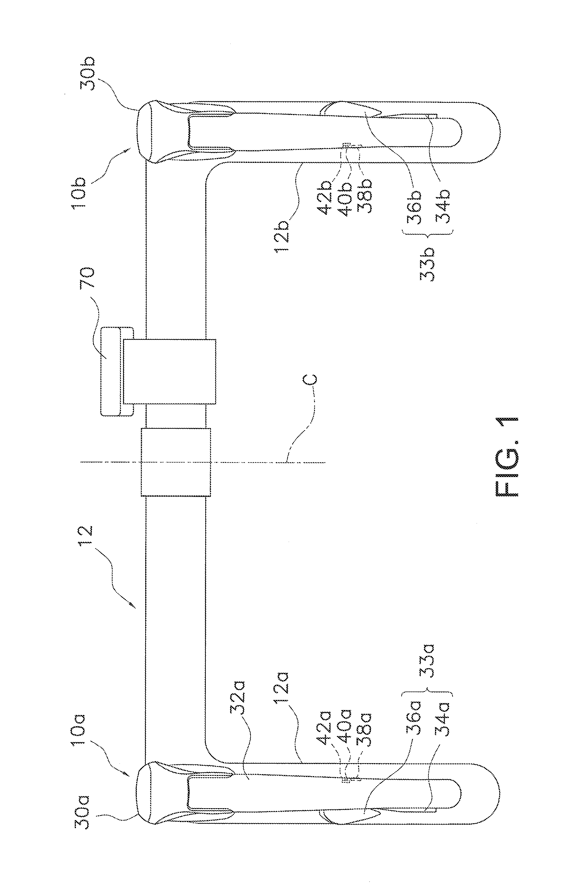
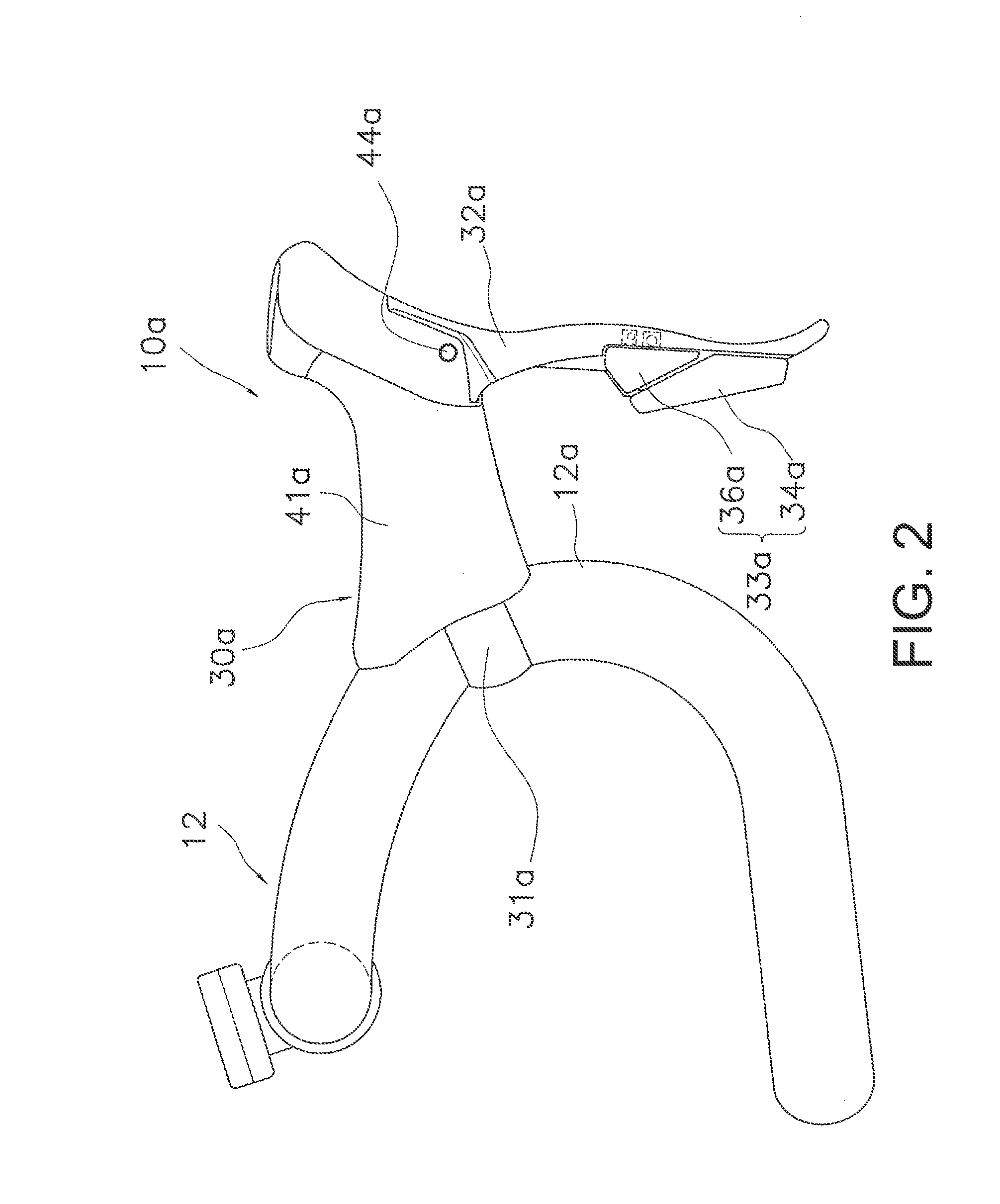
[0041]Referring initially to FIG. 1, a pair of control devices 10a and 10b of a first embodiment are installed on a bicycle handlebar 12 of a bicycle. As shown in FIGS. 1 and 2, the handlebar 12 is a so called drop handlebar. With this type of handlebar 12, the control devices 10a and 10b are installed at each of both ends of the handlebar 12 on curved portions which curve forward and then downward. Here “up”, “down”, “left”, and “right” signify up, down, left and right when a rider (person operating the bicycle) is seated in a saddle (not shown) facing the handlebar 12 with the control devices 10a and 10b installed. Additionally, “inwar...


PUM


Abstract

A control device is configured to be installed on a handlebar of a bicycle and configured to operate a brake device on the bicycle. The control device basically includes a bicycle attachment member, a brake operating member and at least one of a wireless communication unit and a notification unit. The brake operating member is pivotally coupled to the attachment member to pivot about a first axis. The least one of the wireless communication unit and the notification unit is disposed on the brake operating member.

Description

CROSS-REFERENCE TO RELATED APPLICATIONS[0001]This application claims priority to Japanese Patent Application No. 2013-113831, filed on May 30, 2013. The entire disclosure of Japanese Patent Application No. 2013-113831 is hereby incorporated herein by reference.BACKGROUND[0002]1. Field of the Invention[0003]This invention generally relates to a control device. More specifically, the present invention relates to a bicycle control device that is installable on a bicycle handlebar for controlling a brake device on a bicycle.[0004]2. Background Information[0005]Conventional bicycle control devices are known that are capable of controlling a brake device and a gear shift device. (Refer to, for example, Japanese Laid-Open Patent Publication No. 2008-168751). These conventional control devices may have an attachment member capable of being attached to the handlebar, and a brake operating member that may be disposed on the attachment member to move in a given operating direction to actuate t...

Claims


Application Information

Patent Timeline
Patent Type & Authority Applications(United States)
IPC IPC(8): B62L3/02B62M25/08
CPCB62M25/08B62L3/02B62K23/06Y10T74/2028B62J45/00
Inventor GAO, JUN
Owner SHIMANO INC
Learn More