Multipiece hammer for hammer mills

a multi-piece, hammer mill technology, applied in the direction of grain treatment, etc., can solve the problems of reducing the installation time of the assembly or replacement of the hammer on the hammer mill, and achieve the effect of reducing the wear of the bushing or insert, reducing the sticking of the hammer, and prolonging the life of the bushing and the hammer itsel

Inactive Publication Date: 2014-12-04
JACOBS CORP
View PDF11 Cites 9 Cited by
  • Summary
  • Abstract
  • Description
  • Claims
  • Application Information

AI Technical Summary

Benefits of technology

[0009]By using a bushing or insert that extends completely between (and thereby at least partially sealed) between adjacent plates of a hammer mill, small abrasive particles of the material being ground are kept

Problems solved by technology

This arrangement also permits multiple hammer blades to be placed on one insert/bushing, which

Method used


Image

  • Multipiece hammer for hammer mills
  • Multipiece hammer for hammer mills
  • Multipiece hammer for hammer mills

Examples


Embodiment Construction

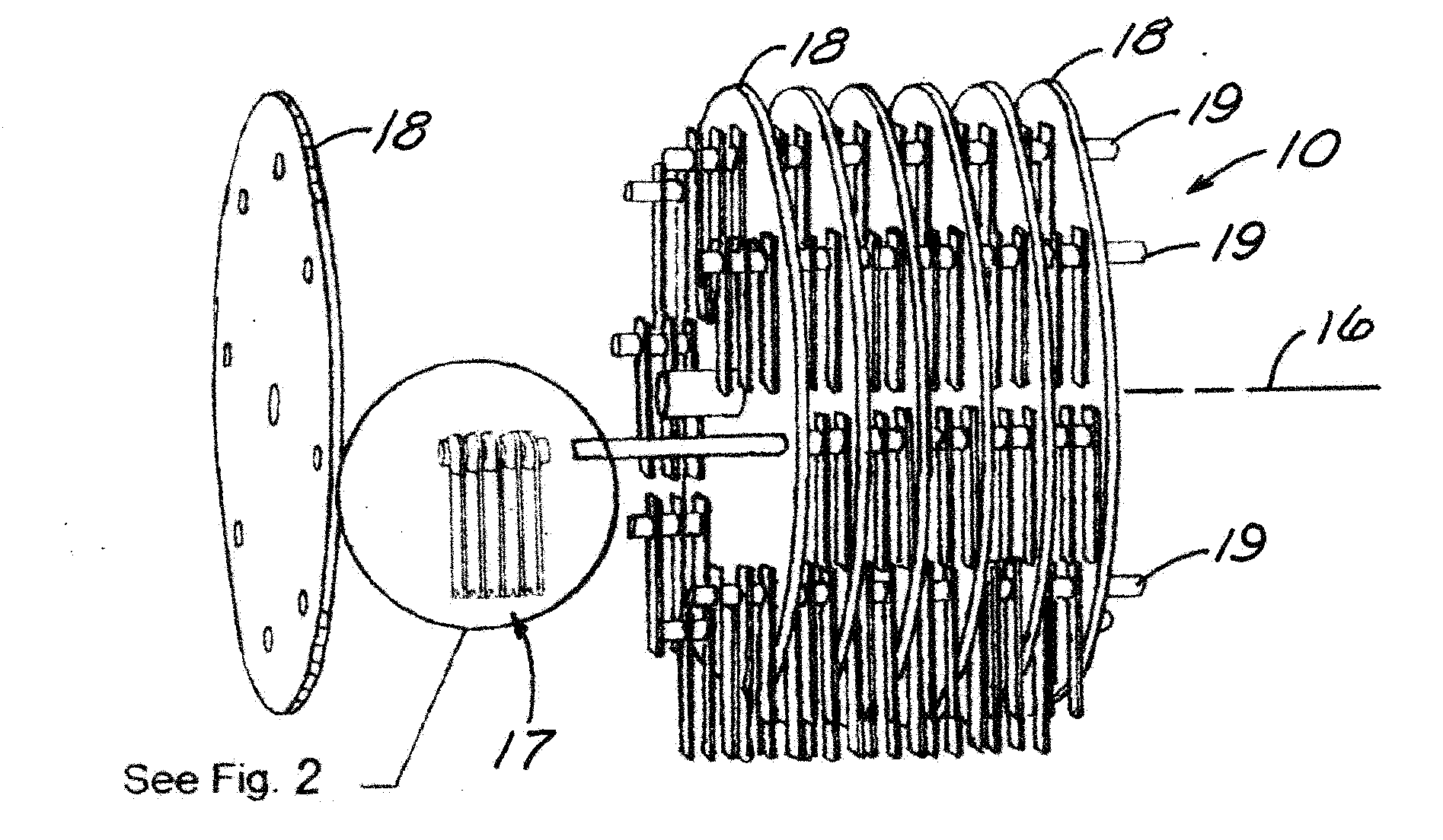
[0022]Referring now to the drawings, where like reference numbers designate identical or corresponding views throughout the several views, FIG. 1 shows a hammer mill assembly 10 constructed in accordance with the present invention.

[0023]The hammer mill assembly 10 would be disposed for rotary movement inside of a perforated housing (not shown) of the type shown in FIGS. 1 and 2 of U.S. Pat. No. 7,419,109 to Rondfelt et al, which is incorporated herein in its entirety. A rotor 14 is journaled in the perforated housing for rotation about a rotor axis 16. The rotor axis 16 extends through at least a portion of the chamber.

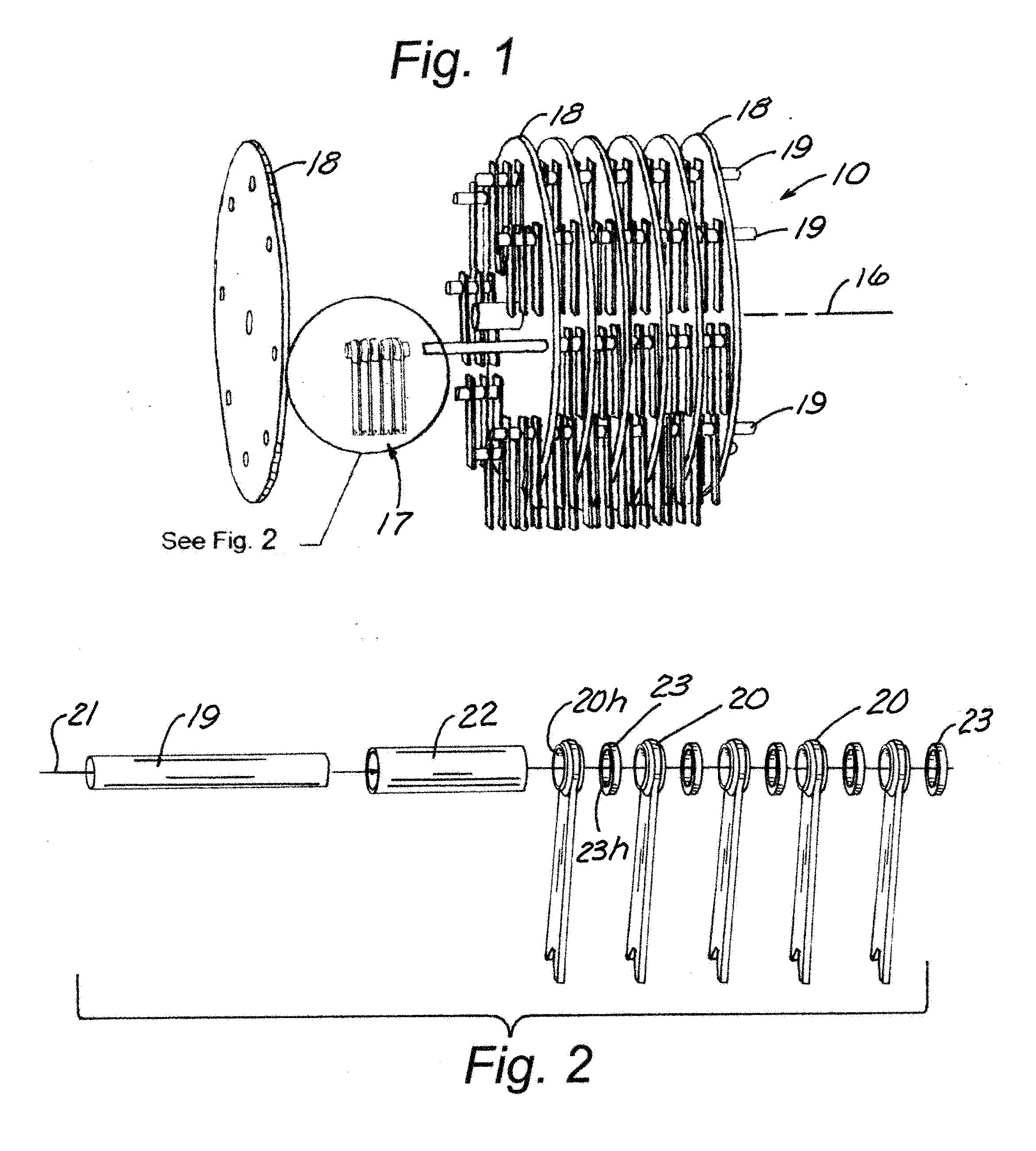
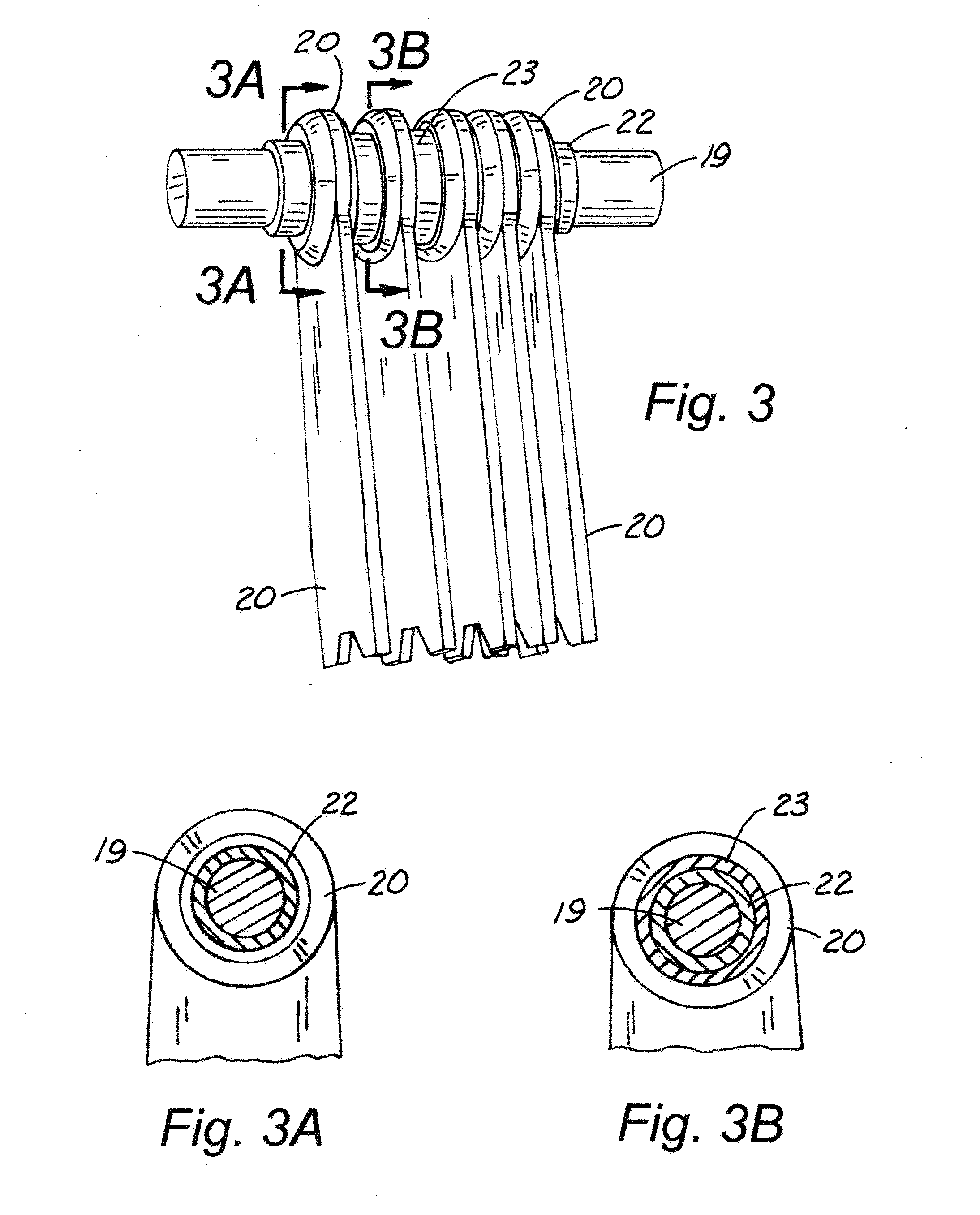
[0024]A screen (not shown) is formed by having a plurality of openings in the housing 11 radially outwardly of the rotor 14. The rotor 14 also includes a plurality of plates 18 rigidly attached thereto. Rods 19 are connected to each one of the plates 18 for rotatably attaching hammers 20 thereto via a bushing / insert structure.

[0025]The rotor 14 has a plurality of pref...


PUM


Abstract

Hammers, including hammer blades, for hammer mills are shown which have an insert bushing press fit into a hole in each hammer blade so that the hammer blades rotate with the bushing around rods being rotated in a circle around a central rotary axis of the rotor of a hammer mill.

Description

TECHNICAL FIELD[0001]This invention relates generally to a hammer mill apparatus and more particularly to one that uses a bushing that extends between adjacent plates of a hammer mill and has one or more hammers press fit onto the bushing.BACKGROUND[0002]Hammers such as those shown in U.S. Pat. No. 7,419,109 to Rondfelt et al. and U.S. Pat. No. 8,104,177 to Plumb need to be replaced periodically. Due to the impact nature of the grinding, the heat treatment of the entire hammer has historically been at low levels to avoid breakage of the hammer. This low level of heat treatment however leads to excessive wear at the hole where the hammer rotates on a hammer mill rod. This phenomenon is sometimes referred to as “hole elongation”. This will also cause excessive wear on the rod itself upon which the hammer rotates about especially once the hammer itself experiences some “hole elongation”.[0003]Another problem is that small particles of the material being ground, such as corn, will tend ...

Claims


Application Information

Patent Timeline
IPC IPC(8): B02C13/26B02C13/28
CPCB02C13/28B02C13/26B02C2013/2808
Inventor PLUMB, CHAD J.
Owner JACOBS CORP
Why Eureka
Try Eureka