
Wind turbine flange connection

a wind turbine and flange technology, applied in the direction of machines/engines, mechanical equipment, reaction engines, etc., can solve the problems of more and heavier bolts in the wind turbine, and more installation time for tightening bolts, so as to improve the transfer of rotational forces, and reduce the need for bolts

Inactive Publication Date: 2014-12-04
SIEMENS GAMESA RENEWABLE ENERGY AS
View PDF5 Cites 3 Cited by
  • Summary
  • Abstract
  • Description
  • Claims
  • Application Information

AI Technical Summary

Benefits of technology

The patent describes a connection system that joins the hub and the nacelle of a wind turbine together to transfer forces. This system addresses a design issue that occurs near the connection point of a rotor blade on the hub. There, the hub's first flange has lower stiffness or a high gradient in stiffness. The technical effect of this technology is to improve the overall stiffness of the hub and to ensure a secure connection between the hub and the rotor blade.

Problems solved by technology

This shows the disadvantage, that more and heavier bolts are needed in a wind turbine and more installation time is needed for tightening the bolts.

Method used


Image

  • Wind turbine flange connection
  • Wind turbine flange connection
  • Wind turbine flange connection

Examples


Embodiment Construction

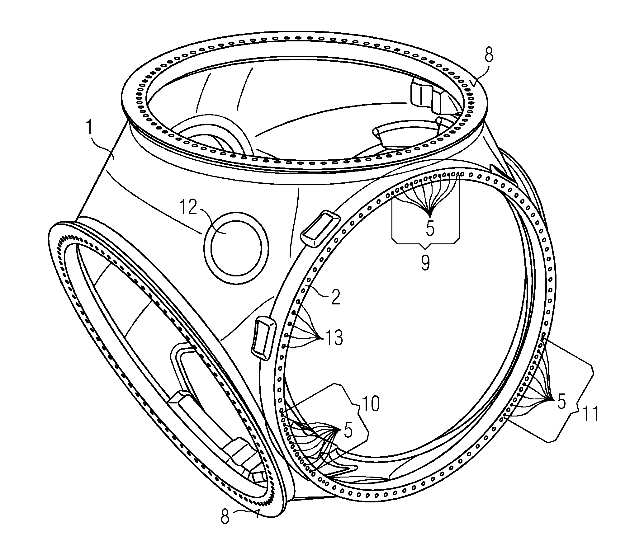
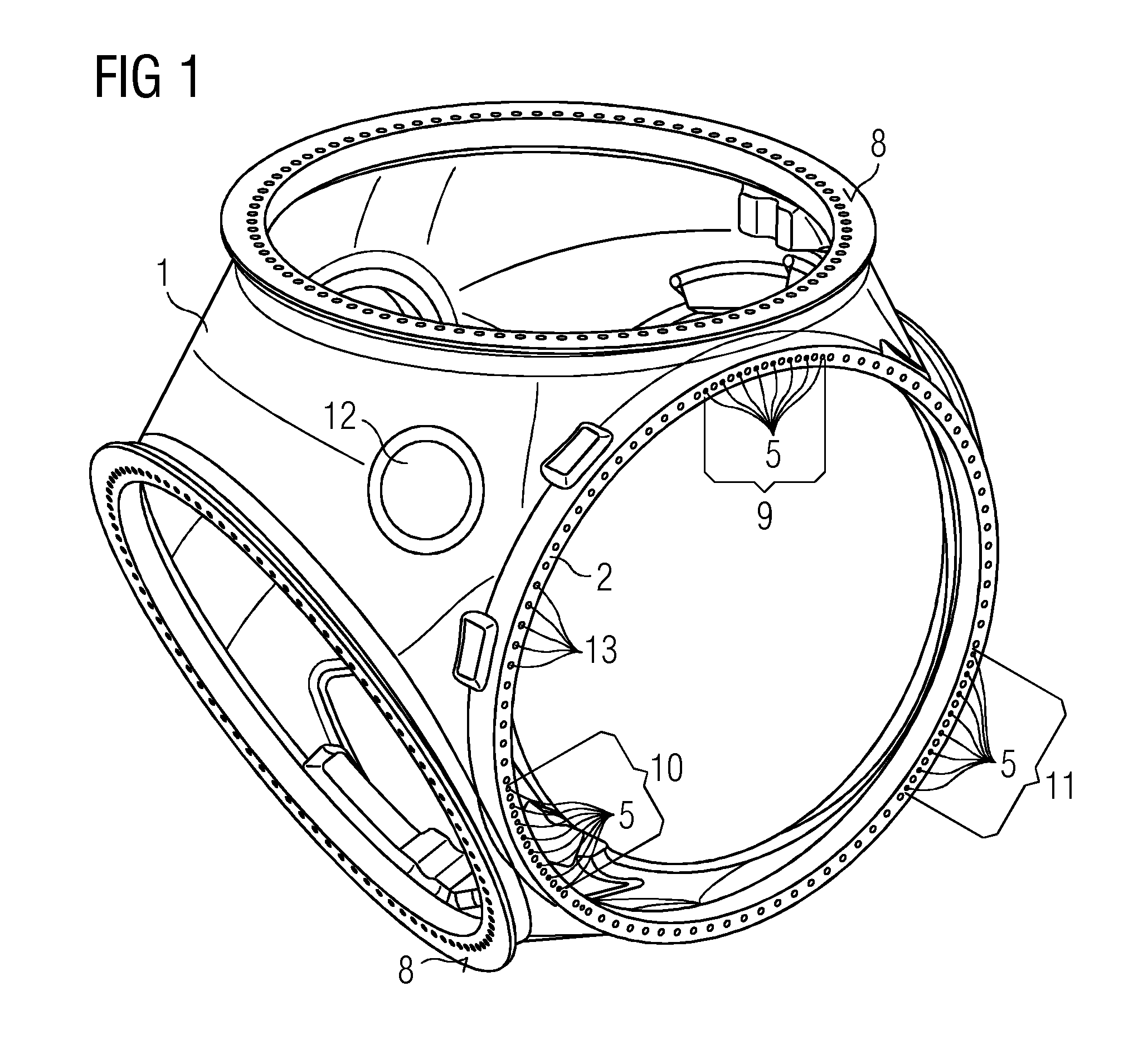
[0093]FIG. 1 shows a hub 1 of a wind turbine. The hub 1 comprises a flange 2 that is used to connect the hub 1 to the nacelle.

[0094]The flange 2 comprises holes 13. The holes 13 are used with connection means 4 like bolts to connect the hub 1 to the nacelle. The flange 2 comprises holes 5 for shear pins 7. The hub 1 comprises connection areas 8 to connect rotor blades to the hub 1.

[0095]The wind interacts with the rotor blades and causes a rotation of the hub 1. The rotation of the hub 1 is transferred via the flange connection to the nacelle. Thus axial forces, rotational forces, and tilting moments are transferred over the flange connection.

[0096]The shear pins 7 are arranged in the holes 5 of the flange 2. The shear pins 7 transfer rotational forces from the first flange 2 of the hub 1 to the second flange 3 of the nacelle.

[0097]The hub 1 comprises man holes 12 for maintenance service. The hub 1 shows a lower stiffness, or high gradient in the stiffness, close to the connection a...


PUM


Abstract

A wind turbine flange connection between a hub and a nacelle of the wind turbine, a wind turbine, a wind turbine hub and a wind turbine nacelle is provided. The hub of the wind turbine comprises a first flange and the nacelle of the wind turbine comprises a second flange. The first flange and the second flange are connected to each other by a number of connection means, to transfer forces between the first flange and the second flange. The first flange comprises a plurality of holes and the second flange comprises a plurality of holes corresponding to the holes in the first flange. Shear pins are arranged in the holes in the flanges to transfer rotational forces between the hub and the nacelle.

Description

CROSS-REFERENCE TO RELATED APPLICATIONS[0001]This application claims priority to EP Application No. 13169501.7, having a filing date of May 28, 2013, the entire contents of which are hereby incorporated by reference.FIELD OF TECHNOLOGY[0002]The following relates to a wind turbine flange connection between the hub and the nacelle of the wind turbine, a wind turbine, a wind turbine hub and a wind turbine nacelle.BACKGROUND[0003]A wind turbine comprises a rotor with rotor blades and a hub. The hub of the wind turbine is connected to the nacelle of the wind turbine. The hub is connected to the main shaft of the wind turbine or to the rotor of an electrical generator at a direct driven wind turbine.[0004]The hub is attached to the nacelle by a flange connection. The flange connection between the hub of a wind turbine and the nacelle comprises a flange at the hub of the wind turbine and a flange at the nacelle of the wind turbine[0005]The hub sided flange and the nacelle sided flange are ...

Claims


Application Information

Patent Timeline
Patent Type & Authority Applications(United States)
IPC IPC(8): F03D11/04
CPCF03D11/04F05B2260/3011F03D15/00F03D13/10F03D1/0691F03D13/20Y02E10/728Y02E10/72F03D80/50
Inventor EBBESEN, HENNINGSHUKLA, AKHILESH
Owner SIEMENS GAMESA RENEWABLE ENERGY AS
Learn More