Afterburner and aircraft engine

Inactive Publication Date: 2014-12-11
IHI CORP
View PDF6 Cites 12 Cited by
  • Summary
  • Abstract
  • Description
  • Claims
  • Application Information

AI Technical Summary

Benefits of technology

[0014]The present invention can sufficiently reduce the pressure loss on the downstream side of the flame stabilizer. Thereby, the present inventio

Problems solved by technology

The mixture of the two flows causes a large pressure loss.
The pressure loss lowers a rate of increase in thrust of t

Method used


Image

  • Afterburner and aircraft engine
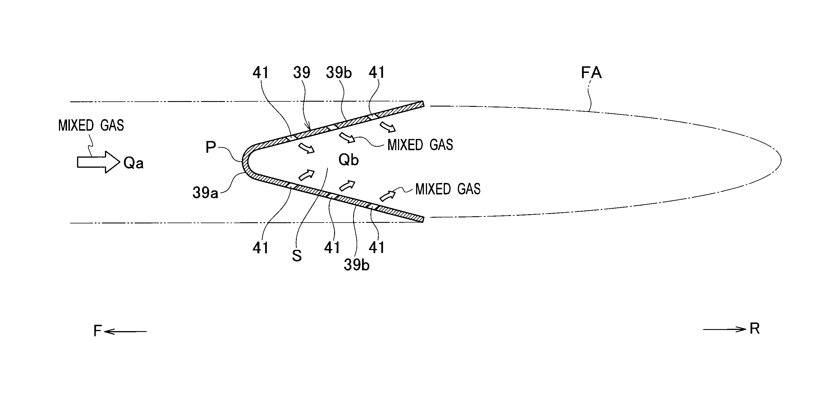
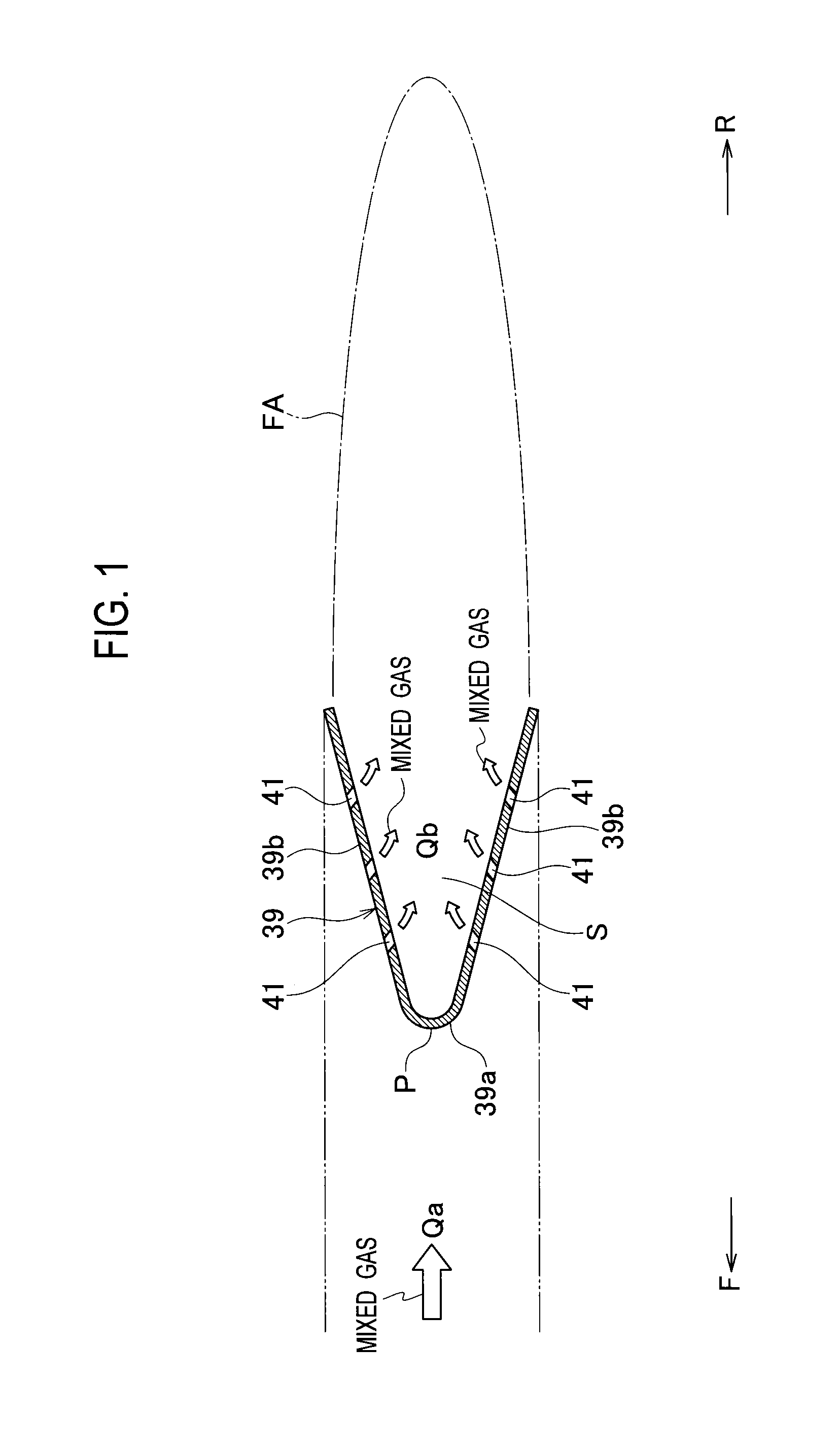
  • Afterburner and aircraft engine
  • Afterburner and aircraft engine

Examples


Embodiment Construction

[0022]The present invention has been made with a result of an analysis using the below-described three-dimensional steady viscosity CFD (Computational Fluid Dynamics) taken into consideration.

[0023]This analysis used an assumed gutter having a V-shaped cross-sectional shape which was opened to a downstream side of the gutter and including multiple through-holes formed only in its two side surface sections. The analysis found a relationship between a ratio Qb / Qa of mass flow rates of mixed gases (a predetermined ratio of mass flow rates in an aircraft engine in operation) and a pressure coefficient on the downstream side of the flame stabilizer. In this respect, Qa denotes amass flow rate of a mixed gas flowing toward the gutter in the aircraft engine in operation, and Qb denotes a mass flow rate of a mixed gas introduced into the gutter through the multiple through-holes in the gutter. FIG. 6 shows the result of the analysis. As shown in the graph, it was learned that as the ratio Q...


PUM


Abstract

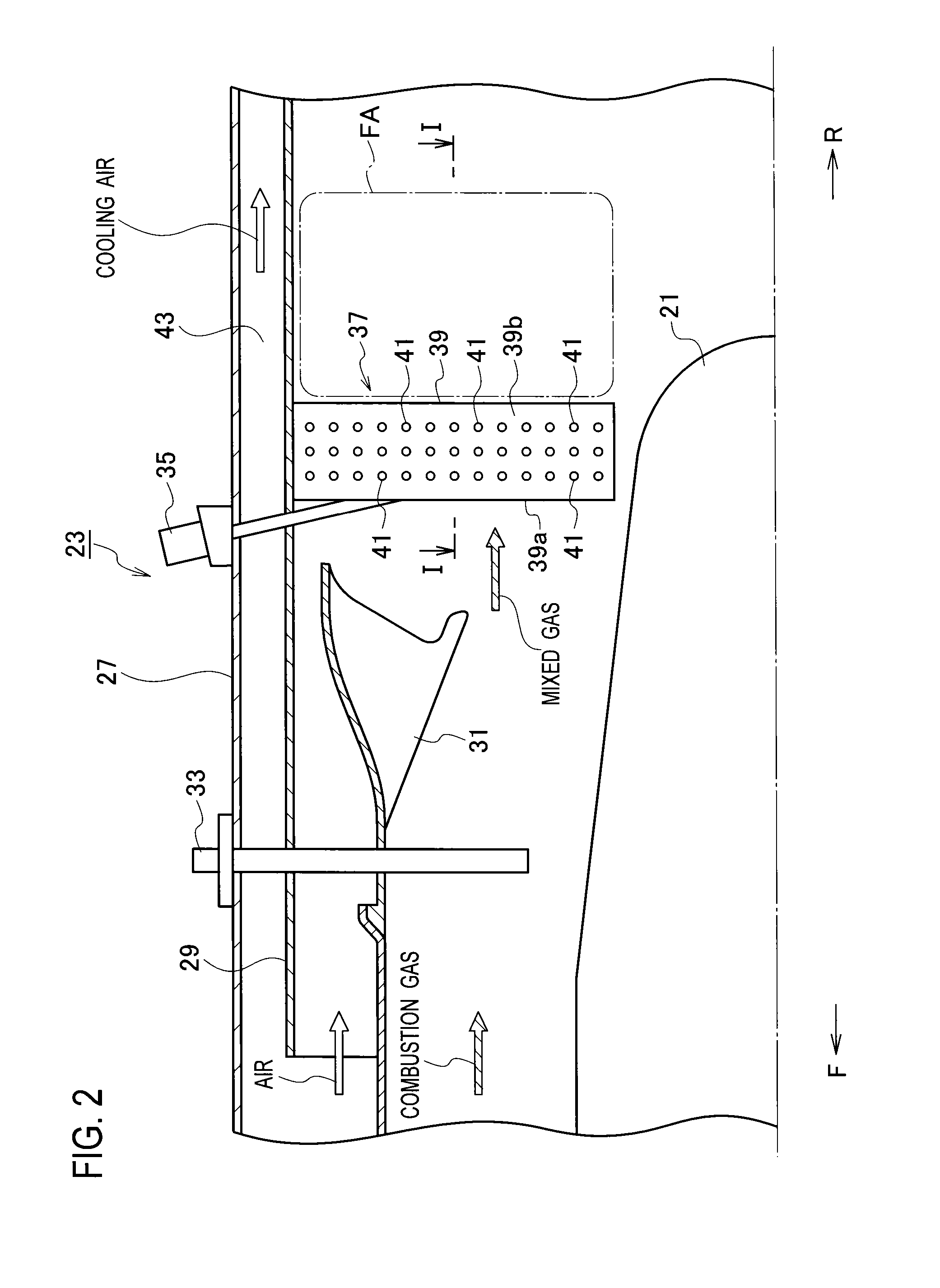
An aircraft engine includes an afterburner which has a flame stabilizer. The flame stabilizer maintains a flame generated from a mixed gas of a combustion gas and air. The flame stabilizer includes multiple gutters each configured to generate a flame stabilization area for the flame on its downstream side. Each gutter is formed from: a curved apex section having a stagnation point; and flat plate-shaped side surface sections integrally formed on the respective two sides of the apex section. Each gutter has a V-shaped cross-sectional shape which is opened to the downstream side. At least one through-hole is formed only in each side surface section of each gutter.

Description

CROSS REFERENCE TO RELATED APPLICATIONS[0001]This application is a continuation application of International Application No. PCT / JP2013 / 055665, filed on Mar. 1, 2013, which claims priority to Japanese Patent Application No. 2012-046319, filed on Mar. 2, 2012, the entire contents of which are incorporated by references herein.BACKGROUND OF THE INVENTION[0002]1. Field of the Invention[0003]The present invention relates to: an afterburner configured to increase thrust of an aircraft engine by burning a mixed gas of a combustion gas (a high-temperature gas) discharged from a core passage of the aircraft engine and air (low-temperature air) discharged from a fan passage of the aircraft engine again while supplying fuel to the mixed gas; and the like.[0004]2. Description of the Related Art[0005]Various research and development programs on afterburners have been conducted in recent years to meet demands for aircraft engines with higher thrust. A configuration and the like of a general afte...

Claims


Application Information

Patent Timeline
IPC IPC(8): F23R3/20
CPCF23R3/20F02K3/11
Inventor TANAKA, SHINJITAKAHASHI, KATSUYOSHIHOSOI, JUN
Owner IHI CORP
Why Eureka
Try Eureka