Magnetoelastic Torque Sensor and Method

a magnetic torque and sensor technology, applied in the field of systems and methods, can solve the problems of false torque value, error-prone configuration of the invention disclosed in the '059 patent, and patents that are susceptible to other factors, so as to improve noise immunity, reduce installation space requirements for secondary sensors, and reduce the effect of weigh

Active Publication Date: 2014-12-11
METHODE ELECTRONICS MALTA
View PDF1 Cites 30 Cited by
  • Summary
  • Abstract
  • Description
  • Claims
  • Application Information

AI Technical Summary

Benefits of technology

[0018]Although shielding is generally considered insufficient to protect or shield external magnetic fields propagating through the shaft, the present invention has the surprising effect that the effects of the near magnetic field are canceled out to a higher extent than with external magnetic field sensors. In particular, the torque sensor according to the aspects of the invention is suitable to suppress disturbances of magnetic fields having very low frequencies down to 0 Hz (DC). The additional disadvantage of the shielding method according to which any deformation of the shield device caused by mechanical impact or extreme temperature change can result in compassing failure is irrelevant, as the shaft is —inherently—conceived not to deform under the normal operating conditions. Furthermore, additional packaging space is not required.
[0059]However, the arrangement inside the at least partially hollow longitudinally extending member (for example hollow flange or hollow shaft) also provides additional unexpected advantages and in particular a much better noise immunity with respect to magnetic field sources. If the magnetic field sensors arranged inside the at least partially hollow longitudinally extending member, they can be placed closer together, while their relative distance with respect to the magnetically active regions on the member can remain the same. The member provides an additional shielding effect, but is inherently stable. Furthermore, all the field sensors can be mounted on a printed circuit board (PCB), thereby providing an automatic alignment of the magnetic field sensors with respect to each other and with respect to the magnetically active region of the member.

Problems solved by technology

Because magnetic fields, in the context of their measurement, are fungible, the sensor taught in the '555 patent may be susceptible to other magnetic field of exterior origin.
In practice, the configuration of the invention disclosed in the '059 patent is error-prone in the presence of locally divergent magnetic fields because the two magnetic field sensors experience different magnitudes of the divergent magnetic fields.
The difference in magnetic fields between the two magnetic field sensors originating from a near field source combines non-uniformly with torque induced magnetic fields and leads to a false torque value.
There are numerous other types of near field sources that can compromise an accurate torque-dependent field measurement.
Another would be the nearby presence of a ferromagnetic structure that distorts the shape and direction of the earth's magnetic field, creating a localized area in which the magnetic flux is concentrated in an undesirable direction.
While the shielding method noted above can be effective for external magnetic fields perpendicular to the axial direction of a shield in the form of a tube, this shield is very vulnerable to external magnetic fields in the axial direction of the tube which is open at both ends.
Flux director structures typically operate by gathering the radial flux component of the torque dependent magnetic field, and are therefore well suited for rejecting axially directed flux of external origin, however, flux directors tend to be susceptible to external fields perpendicular to the axis of the shaft.
However, such a combination has other shortcomings that limit its desirability in many applications including cost and packaging within the design.
Frequently, demagnetization is not perfect, and there remains a remanent magnetic field in the column or shaft after the MPI process.
This relatively large external magnetic field can be directly transferred to the field sensors inside the shield, and can be non-uniformly summed with the torque-induced magnetic fields, corrupting the torque measurement.
This means that there is no totally effective way to protect or shield external magnetic fields propagating through the shaft with current techniques.
An additional disadvantage of the shielding method is that any deformation of the shield device caused by mechanical impact or extreme temperature change can affect the relative position of the field sensors and the shield, which can lead to unbalancing of far field values between two sensor fields operating in pairs that are oppositely oriented.
This would result in compassing failure.
Furthermore, in most torque sensor applications, packaging space is limited, and in many cases there is no room for a shield or flux director.
In addition, the added financial cost for those components is not insignificant because materials with high permeability tend to have high percentages of nickel, the pricing of which is quite volatile.
One of the major challenges consists in measuring torque in a shaft having external magnetic fields down to very low frequencies.
The above prior art solutions are generally not suitable to eliminate disturbances from magnetic fields at very low frequencies down to almost constant values (DC-values).
The additional disadvantage of the shielding method according to which any deformation of the shield device caused by mechanical impact or extreme temperature change can result in compassing failure is irrelevant, as the shaft is —inherently—conceived not to deform under the normal operating conditions.
Torque may be limited for the purpose of protecting a load from damage or preventing the stalling of an internal combustion engine.

Method used


Image

  • Magnetoelastic Torque Sensor and Method
  • Magnetoelastic Torque Sensor and Method
  • Magnetoelastic Torque Sensor and Method

Examples


Embodiment Construction

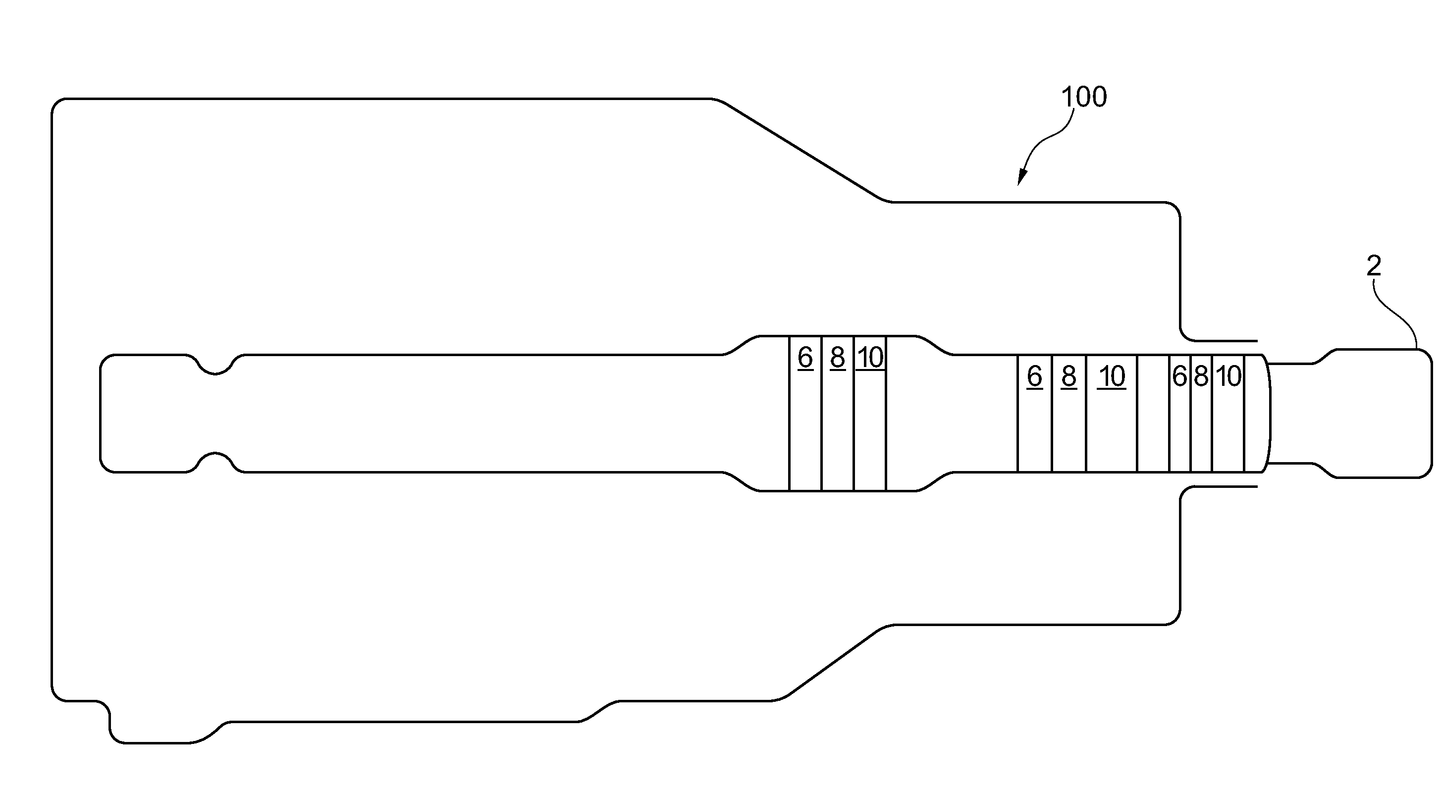
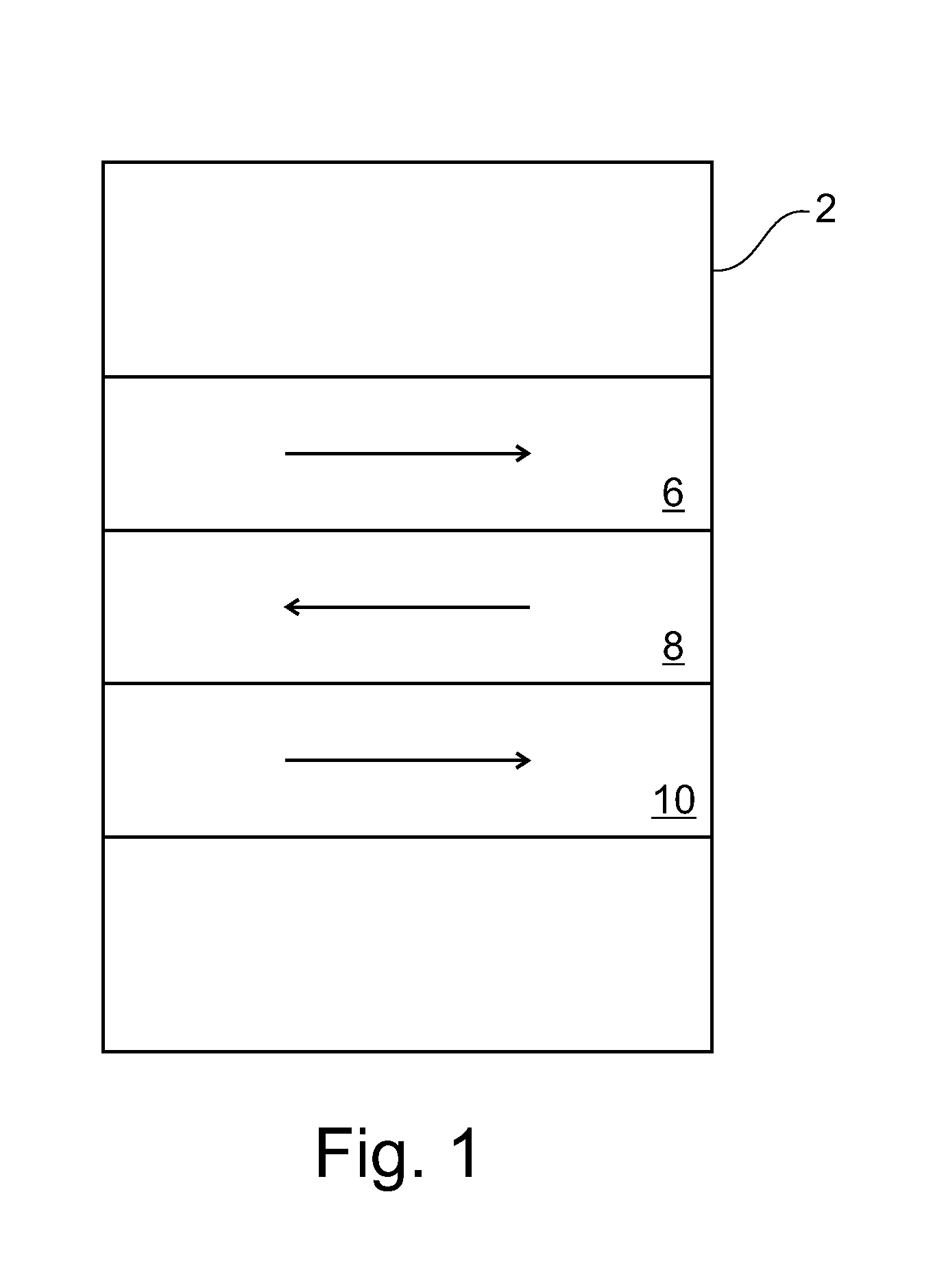
[0067]FIG. 1 is a schematic diagram showing a hollow or partially hollow shaft 2 having three magnetized regions 6, 8, 10 according to an embodiment of the invention. The shaft 2 is magnetically conditioned so as to provide the regions 6, 8, 10, having remanent circumferential magnetizations in the shaft 2. The arrows indicate the direction of the circumferential magnetization. In this embodiment, regions 6 and 10 have the same direction, and region 8 which is in the middle has a magnetization in the opposite direction.

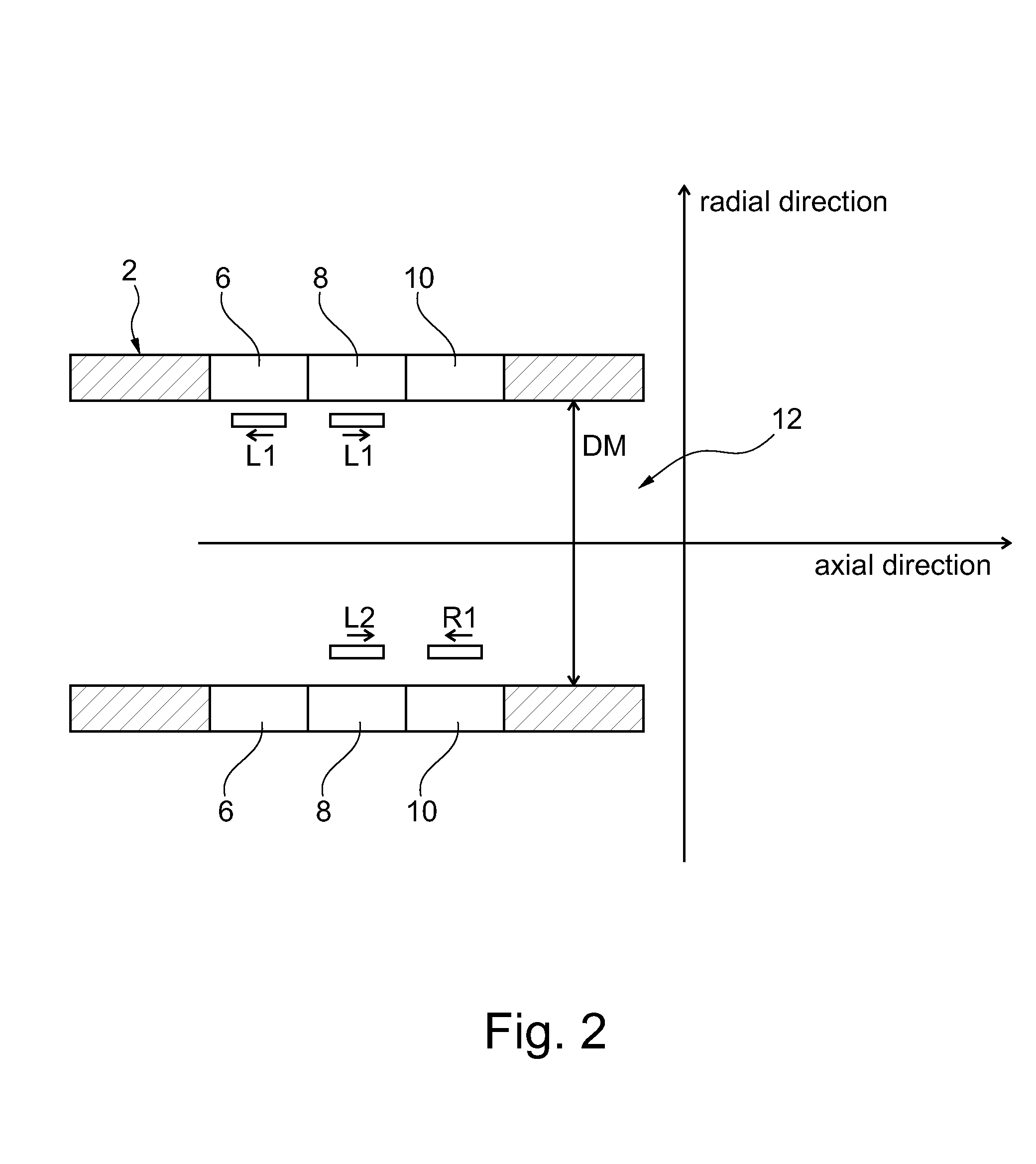
[0068]FIG. 2 is a schematic diagram showing the placement of primary magnetic field sensors C1 and C2 and secondary magnetic field sensors R and L inside the hollow shaft 2 (longitudinally extending member) having three magnetized regions 6, 8, 10. The shaft 2 has a cavity 12 in which the sensors C1, C2, R and L can be arranged. The primary and secondary magnetic field sensors C1, C2, R and L are placed close to the inner surface of the shaft 2 (i.e. the inner surface...


PUM

PropertyMeasurementUnit
frequenciesaaaaaaaaaa
distanceaaaaaaaaaa
distanceaaaaaaaaaa

Abstract

The invention provides a method for reducing the noise in a signal from a torque sensor caused by near magnetic field sources. The torque sensor comprises: a at least partially hollow longitudinally extending member, a magneto-elastically active region effective at the inner surface of the member in such a manner that torque applied to the member is proportionally transmitted to the active region, the active region comprising at least one region magnetically polarized such that the magnetized polarity becomes increasingly helically shaped as the applied torque increases; a plurality of primary magnetic field sensors arranged approximate the at least one region for outputting a first signal corresponding to a torque-dependent magnetic flux emanating from the active region; at least one secondary magnetic field sensor axially spaced in a first direction by a pre-determined first distance from the plurality of primary magnetic field sensors for outputting a second signal corresponding to an ambient magnetic flux emanating from a near magnetic field source; at least one secondary magnetic field sensor axially spaced in a second direction opposite the first direction by a pre-determined second distance from the plurality of primary magnetic field sensors for outputting a third signal corresponding to the ambient magnetic flux emanating from the near magnetic field source; means for adjusting the first signal using the second and the third signals thereby compensating for the effects of the near magnetic field source, characterized in that the primary and secondary magnetic field sensors are arranged inside the longitudinally extending member.

Description

FIELD OF THE INVENTION[0001]The invention is related in general to systems and methods involving the use of magnetic field sensors, and in particular the invention is related to systems, methods and apparatuses involving sensors and circuits that cancel magnetic field noise while measuring torque-induced magnetic fields.DESCRIPTION OF THE RELATED ART[0002]US Pat. No. 2012 / 0074933 A1, the disclosure of which is incorporated herein by reference in its entirety, discloses torque sensors and methods for reducing the noise in a signal from a torque sensor caused by near magnetic field sources using magnetic field sensors which are arranged proximate to a longitudinally extending member with a magneto-elastically active region directly or indirectly attached to or forming a part of the surface of the member in such a manner that torque applied to the member is proportionally transmitted to the active region. The active region comprises at least one region magnetically polarized such that ...

Claims


Application Information

Patent Timeline
Patent Type & Authority Applications(United States)
IPC IPC(8): G01L3/10G01R33/00
CPCG01R33/0029G01L3/105G01L3/102
Inventor BARRACO, IGNAZIOMIR, ASSEDGIE IBL, JOHANNES
Owner METHODE ELECTRONICS MALTA
Why Eureka
Try Eureka