Power electronic converter

a technology of electronic converter and power supply, applied in the direction of dc-ac conversion without reversal, electric power transfer ac network, active power filtering, etc., can solve the problems of increasing the footprint of the associated power station, introducing unwanted power changes, and affecting the quality of transmitted power

Inactive Publication Date: 2014-12-11
ALSTOM TECH LTD
View PDF12 Cites 21 Cited by
  • Summary
  • Abstract
  • Description
  • Claims
  • Application Information

AI Technical Summary

Problems solved by technology

In addition, the connection of grid-connected renewable resources, such as wind parks and solar farms, to the power grid via DC to AC voltage source converters can lead to the introduction of unwanted power changes.
These power changes may lead to grid instability and thereby affect the quality of the transmitted power in the power grid, which...

Method used


Image

  • Power electronic converter
  • Power electronic converter
  • Power electronic converter

Examples


first embodiment

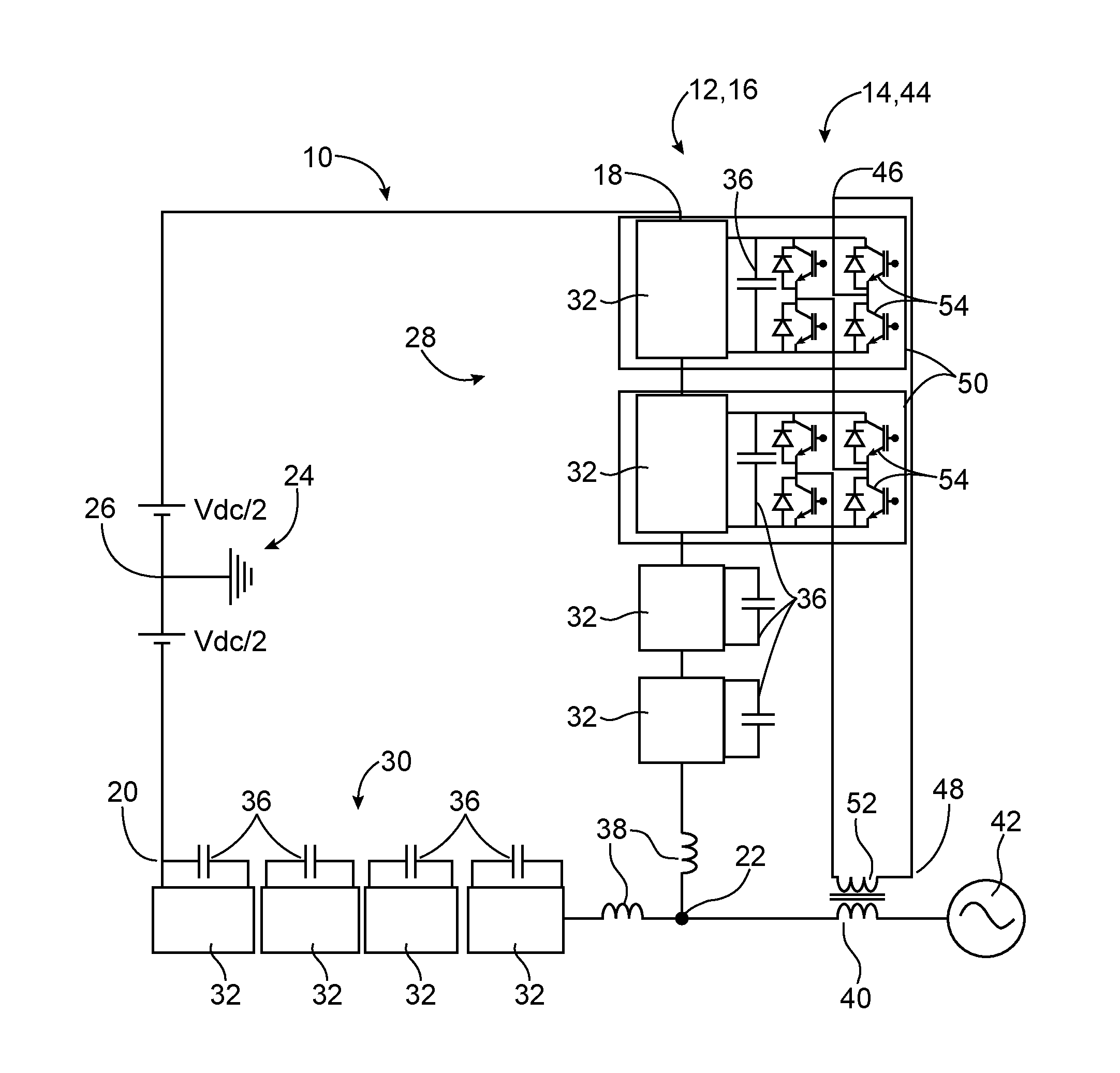
[0043]FIG. 1 shows a power electronic converter 10 according to the invention.

[0044]The power electronic converter 10 comprises a primary converter unit 12 and an auxiliary converter unit 14.

[0045]The primary converter unit 12 includes a primary converter limb 16, which includes first and second DC terminals 18,20 and an AC terminal 22.

[0046]In use, the first DC terminal 18 is connected to a positive terminal of a DC network 24 carrying a voltage of +Vdc / 2, while the second DC terminal 20 is connected to a negative terminal of the DC network 24 carrying a voltage of −Vdc / 2. The DC network 24 includes a mid-point connection 26 to ground.

[0047]The primary converter limb 16 defines first and second limb portions 28,30. In the primary converter limb 16, the first limb portion 28 includes a plurality of primary modules 32 connected in series between the first DC terminal 18 and the AC terminal 22, while the second limb portion 30 includes a plurality of primary modules 32 connected in se...

second embodiment

[0089]FIG. 5 shows a power electronic converter 110 according to the invention. The primary converter unit 112 includes three primary converter limbs 116, while the auxiliary converter unit 114 includes three auxiliary converter limbs 144. Each of the primary and auxiliary converter limbs 116,144 in FIG. 5 is respectively similar in structure and operation to the primary and auxiliary converter limbs 16,44 of FIG. 1 except that the auxiliary converter limbs 144 are connected in parallel with each other and that, in use, the AC terminal 122 of each primary converter limb 116 is connected to a respective phase of a three-phase AC network 142.

[0090]In the three-phase power electronic converter 110, the components of each primary converter limb 116 operates independently of that of the other primary converter limbs 116 and therefore only directly affects the phase connected to the respective AC terminal 122, and has minimal influence on the phases connected to the AC terminals 122 of th...

third embodiment

[0092]A power electronic converter according to the invention is similar in structure and operation to the power electronic converter 10 of FIG. 1, except that each limb portion further includes a secondary switching element connected in series with the primary modules between the respective DC terminal and the AC terminal.

[0093]It is envisaged that, in other embodiments, the number of series-connected secondary switching elements in each limb portion may increase depending on the required voltage rating of each limb portion.

[0094]In use, the secondary switching element of each limb portion is operated to switch the respective limb portion in and out of circuit during power conversion between the AC and DC networks. This is advantageous because it reduces the voltage range that the chain-link converter of each limb portion would be required to generate. This in turn allows the number of components in each limb portion to be minimized, and thereby reduce the overall size of the prima...


PUM


Abstract

A power electronic converter for high/medium voltage direct current power transmission and reactive power compensation comprises a primary converter unit and an auxiliary converter unit, the primary converter unit including at least one primary converter limb including first and second DC terminals for connection in use to a DC network and an AC terminal, the or each primary converter limb defining first and second limb portions, each limb portion including at least one primary module, the or each primary module including at least one primary switching element connected to an energy storage device, the auxiliary converter unit including at least one auxiliary converter limb including at least one auxiliary module including a plurality of auxiliary switching elements connected to the energy storage device of a corresponding primary module in the first limb portion of a respective primary converter limb, the primary switching elements of the primary modules being controllable in use to switch the respective energy storage device in and out of circuit to generate a voltage waveform at the respective AC terminal.

Description

TECHNICAL FIELD AND PRIOR ART[0001]This invention relates to a power electronic converter for high / medium voltage direct current power transmission and reactive power compensation.[0002]Power changes in a power grid may occur as a consequence of, for example, grid disturbances or line faults, or as a result of “smart” power grids dynamically responding to consumer demand by effectively changing the grid operating conditions. In addition, the connection of grid-connected renewable resources, such as wind parks and solar farms, to the power grid via DC to AC voltage source converters can lead to the introduction of unwanted power changes. These power changes may lead to grid instability and thereby affect the quality of the transmitted power in the power grid, which has economic implications for the power supplier and the end user.[0003]A solution for controlling power quality is a unified power flow controller (UPFC), which is capable of regulating the quality of the transmitted powe...

Claims


Application Information

Patent Timeline
IPC IPC(8): H02J3/36H02J3/18
CPCH02J3/18H02J3/36H02J3/1857H02M1/12H02M7/483H02M7/49Y02E40/20H02M7/4835
Inventor HASSAN, FAINAN, AHMED, ABDUL, MAGUEED MOHAMMED
Owner ALSTOM TECH LTD
Why Eureka
Try Eureka