
System and Method for Controlling an Electronic Device

Inactive Publication Date: 2014-12-11
SULLIVAN SCOTT
View PDF21 Cites 26 Cited by
  • Summary
  • Abstract
  • Description
  • Claims
  • Application Information

AI Technical Summary

Benefits of technology

The patent describes a system for controlling a head-worn computer using a tooth-tapping input method. This allows users to control various functions of the computer by tapping their teeth in a unique pattern. The computer detects the sound and vibrations created by the tapping, and uses a special algorithm to determine the exact pattern of taps. This unique signature is then compared to pre-stored commands, and the computer performs the required action. The system can be used in various locations and situations, providing a discreet and efficient way to control the device. Additionally, The patent also describes how the tooth-tapping system can be used to control music being played through the headphones.

Problems solved by technology

Although Google's Glass device appears to have opened up a new chapter of really cool and potentially useful smart computing devices, it is not without some operational issues that may be difficult to overcome.
As is well known by users of various “smart” devices, there are many locations and daily situations where a user may find it inappropriate or awkward to voice commands out-loud.
This may work well for a short while, but if the device requires prolonged input interaction from the user, he or she is going to get real tired real quick holding their hand up against their head as they operate and interactive with their computer device.

Method used


Image

  • System and Method for Controlling an Electronic Device
  • System and Method for Controlling an Electronic Device
  • System and Method for Controlling an Electronic Device

Examples


Embodiment Construction

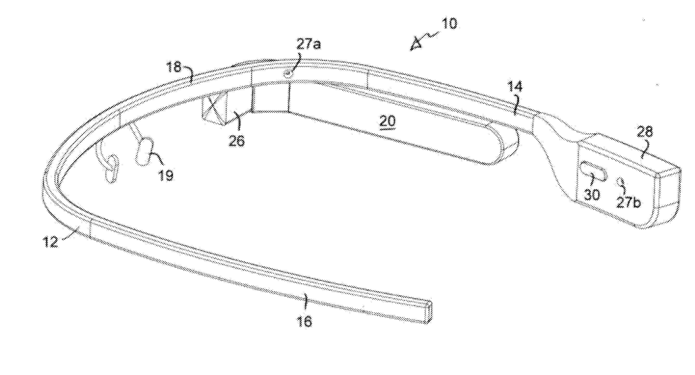
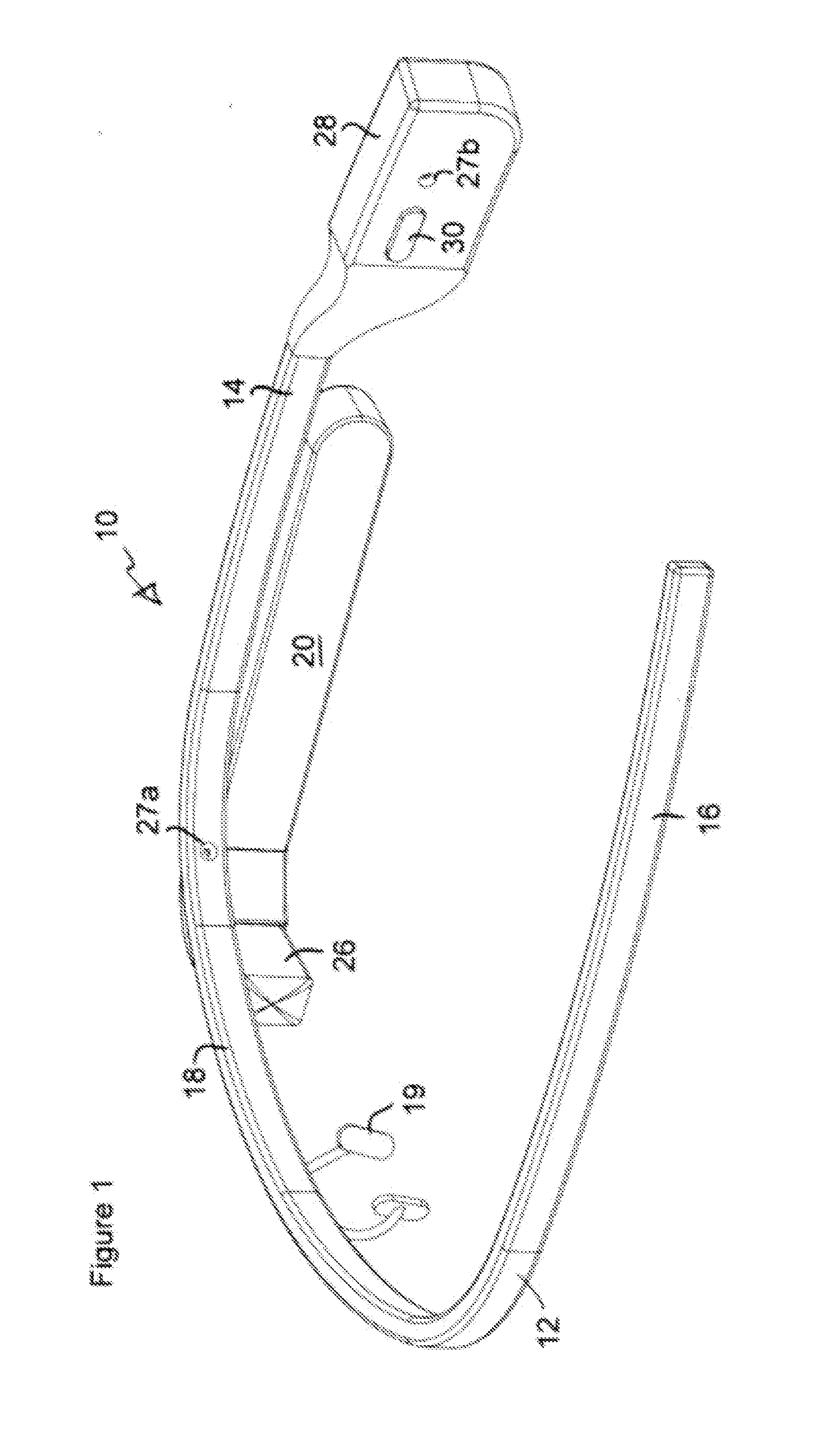
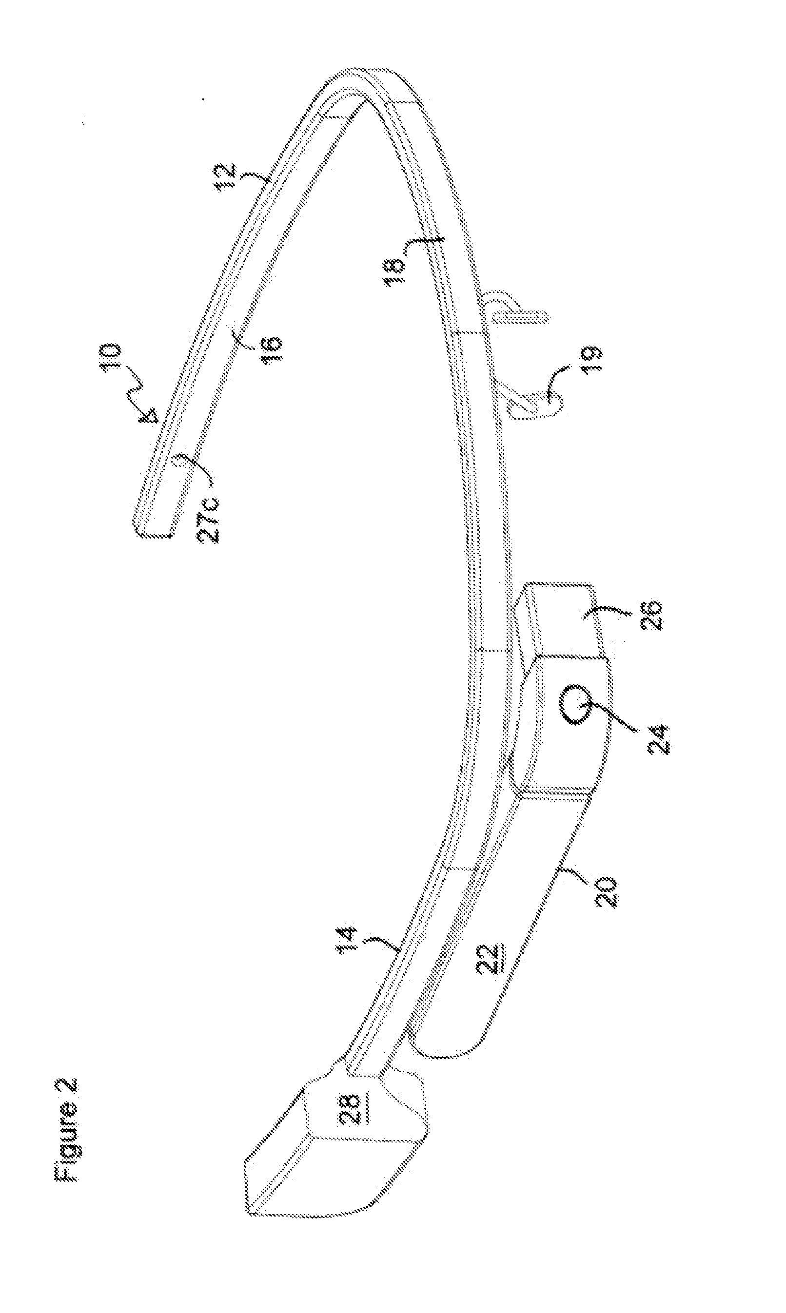
[0016]Referring to the Figures, an exemplary head-mounted computer device 10, similar to Google's Glass device is shown, including a generally U-shaped frame structure 12 that defines a right arm 14, a left arm 16 and a front member 18. Similar to conventional vision-correction glasses, a generally conventional nose support 19 is secured to front member 18 and is used to comfortably rest on a user's nose to help support device 10 on a user's face. Similarly, right arm 14 and left arm 16 are sized and shaped to comfortably engage the user's ears to help firmly hold frame 12 to the user's head. A first housing 20 is secured to light arm 14 and includes a touchpad input device 22, a camera (and lens) 24, a Heads-Up-Display (HUD) 26, a microphone 27a and other computer-related controlling circuitry and / or batteries (not shown). A second housing 28 is also secured to right arm 14 and includes a bone-conduction transducer 30 and other controlling circuitry and / or batteries (not shown). In...


PUM


Abstract

For use with a head-worn computer, such as Google's Glass device, a user-generated tooth-tapping based input is used to control various and select computer operations during its use. The user simply opens and closes their jaw slightly so that they tap their right side pair of canine teeth, their left side pair of canine teeth, or all their teeth together to generate a sound and a vibration. This sound and vibration generated by a single tooth tap or any combination thereof is detected by at least one microphone located on the head-worn computer, and according to other embodiments of this invention two or more microphones and / or vibration-detection sensors. The computer receives the tapping sound signals from the microphone and uses controlling circuitry and / an algorithm to determine the exact tap-sequence and time between taps to establish a “command signature”, specific to each particular tap-sequence. From this, the computer compares the command signature with a corresponding command or action stored in the onboard memory and then performs that command or action, as required. The user can effectively and discretely control many operations of the head-worn computer merely through tooth tapping.

Description

CROSS-REFERENCE TO RELATED APPLICATION[0001]This application claims the benefit of U.S. Provisional Application No. 61 / 832,856, filed Jun. 8, 2013, entitled “ Dentine-Based Computer Input System and Method for Using Teeth Tapping to Control a Computer.”BACKGROUND OF THE INVENTION[0002]1) Field of the Invention[0003]The present invention generally relates to input controllers for controlling the operation of a computer and running applications, and more particularly, to such an input controller for use with head-worn computers, such as the “Google Glass” device.[0004]2) Discussion of Related Art[0005]The trackball input device was invented in 1952 by Tom Cranston. Eleven years later, Douglas Engelbart and Bill English invented the first mouse at the Stanford Research Institute. As is well known, these two devices along with the keyboard would make up for decades to follow the most commonly used input devices for controlling the operation of computers. Other input devices would be int...

Claims


Application Information

Patent Timeline
IPC IPC(8): G05B15/02G06F3/16
CPCG06F3/165G05B15/02G06F3/011H04R1/46H04M1/6058G06F1/163G02B2027/0178
Inventor SULLIVAN, SCOTT
Owner SULLIVAN SCOTT
Learn More