Functional retainer
An orthodontic device and partial energy technology, applied in orthodontics, medical science, orthodontics, etc., can solve problems such as poor orthodontic effect of the orthodontic device, and achieve the effect of improving the effect
- Summary
- Abstract
- Description
- Claims
- Application Information
AI Technical Summary
Problems solved by technology
Method used
Image
Examples
Embodiment 1
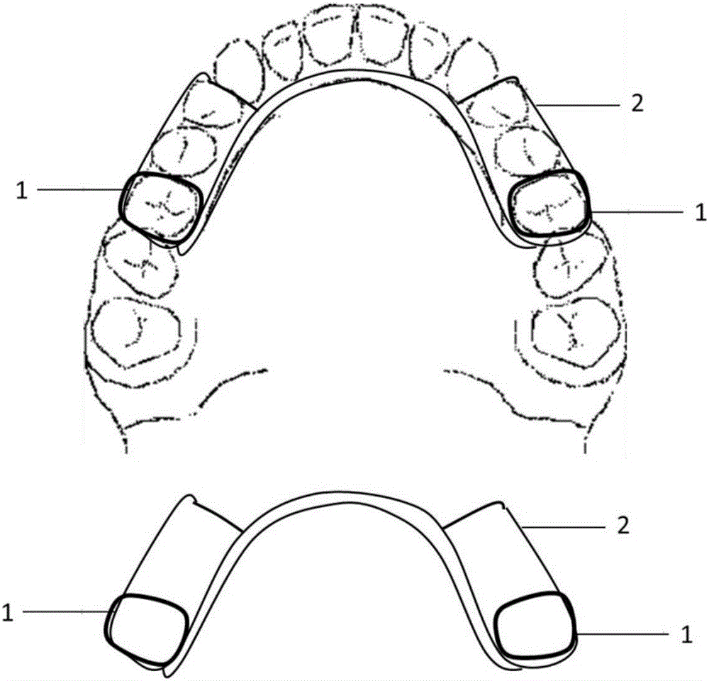
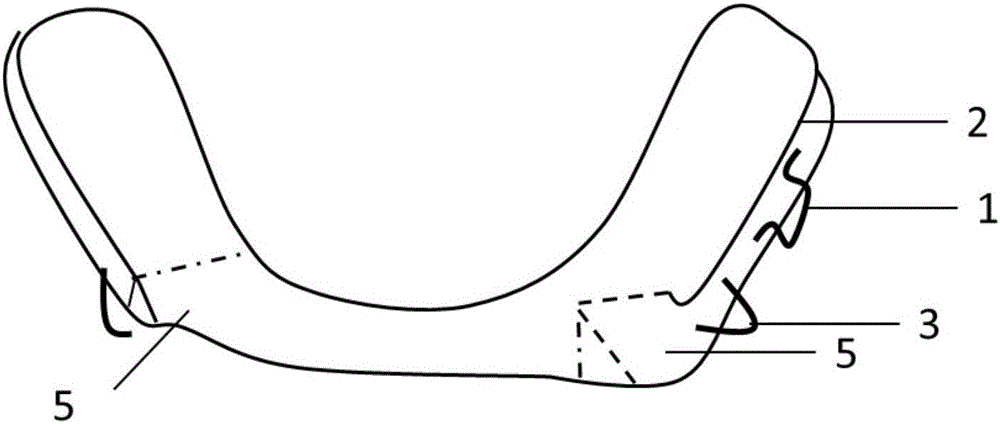
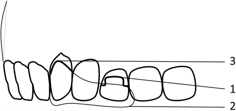
[0032] A partial occlusion functional orthodontist, comprising a maxillary part and a mandibular part, the maxillary part includes arrow clips 1 fixed on the molars on the left and right sides, single-wall clips 3 fixed on the bicuspids on the left and right sides, and connecting The occlusal pad 2 of the arrow card 1 and the single wall card 3, the mandibular part includes the interproximal hook 4 fixed on the incisors and canines, the arrow card 1 fixed on the canines on the left and right sides, and the connecting arrow card 1 and The occlusal pad 2 of the interproximal hook 4, the maxillary part and the mandibular part each include a guide slope 5, the guide slope 5 is located inside the bicuspid teeth, and the angle between the guide slope 5 and the occlusal surface is 40-60 degrees, and the direction of inclination is the same as that of the occlusal surface. The jaw deviates in the opposite direction.
Embodiment 2
[0034] A method of making a partial occlusion functional aligner:
[0035] a. Take the impressions of the upper and lower dentition respectively, and fill the plaster model;
[0036] b. Take the occlusal record: record the occlusal relationship when the upper and lower jaw midlines are aligned with a wax film in the patient's mouth, remove the wax film, put it on the model for verification, and use the facebow transfer technology to strictly follow the occlusal relationship recorded on the wax film. The plaster model is fixed on an adjustable articulator;
[0037] c. Make arrowhead card 1 and single wall card 3 on the buccal sides of the upper jaw, and make interproximal hook 4 on the adjacent surface of the incisors and canines in the lower jaw;
[0038] d. The production scope of occlusal pad 2: including the occlusal surface of the upper jaw and the bilateral occlusal surface of the mandible; the production requirements of occlusal pad 2: first complete the upper occlusal ...
Embodiment 3
[0040] A partial occlusion functional orthodontic device, comprising a maxillary part and a mandibular part. The maxillary part includes arrow clips 1 fixed on the molars on the left and right sides. The molars on the left and right sides correspond to each other and are first molars and / or On the second molars, the single-wall clamps 3 fixed on the left and right sides of the bicuspids are located on the inner guide slope 5 of the bicuspids. The angle between the guide slope 5 and the occlusal surface is 45 degrees, and the direction of inclination is opposite to that of the partial jaw. The arrow card 1 is adjacent to the single wall card 3; the guide slope 5 is adjacent to the single wall card 3; the guide slope 5, the single wall card 3 and the arrow card 1 are connected through the occlusal pad 2; The interproximal hook 4 on the tooth, the arrow clip 1 fixed on the canines on the left and right sides, and the guiding slope 5 on the inner side of the bicuspid teeth. The ang...
PUM
 Abstract
Description
Claims
Application Information
 - R&D
- Intellectual Property
- Life Sciences
- Materials
- Tech Scout
- Unparalleled Data Quality
- Higher Quality Content
- 60% Fewer Hallucinations
Browse by: Latest US Patents, China's latest patents, Technical Efficacy Thesaurus, Application Domain, Technology Topic, Popular Technical Reports.
© 2025 PatSnap. All rights reserved.Legal|Privacy policy|Modern Slavery Act Transparency Statement|Sitemap|About US| Contact US: help@patsnap.com


