
System and method for estimating and providing dispatchable operating reserve energy capacity through use of active load management

a technology of active load management and operating reserve energy capacity, applied in the field of system and method for estimating and/or providing dispatchable operating reserve energy capacity for electric utilities, can solve the problems of uneconomical storage of power, unsatisfactory fluctuations in line frequency, and additional costs for the utility

Active Publication Date: 2014-12-11
LANDISGYR TECH INC
View PDF8 Cites 11 Cited by
  • Summary
  • Abstract
  • Description
  • Claims
  • Application Information

AI Technical Summary

Benefits of technology

The present invention is about a system and method for estimating and providing dispatchable operating reserve energy capacity for an electric utility. This helps to ensure that the utility has enough reserve capacity to meet its energy needs or to make it available to the general power market. The invention uses active load management to manage the demand for energy within the utility's service area, reducing fluctuations in line frequency. Overall, the invention helps to optimize energy supply and demand, improving the efficiency and reliability of electric power generation and supply.

Problems solved by technology

Such variation in demand can cause undesired fluctuations in line frequency if not timely met.
However, because power cannot be economically stored, a utility must regularly either bring new capacity on-line or take existing capacity off-line in an effort to meet demand and maintain frequency.
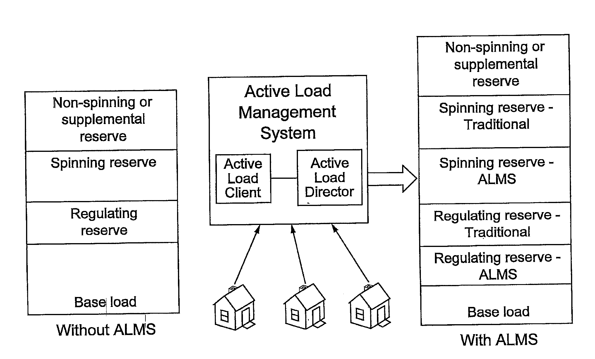
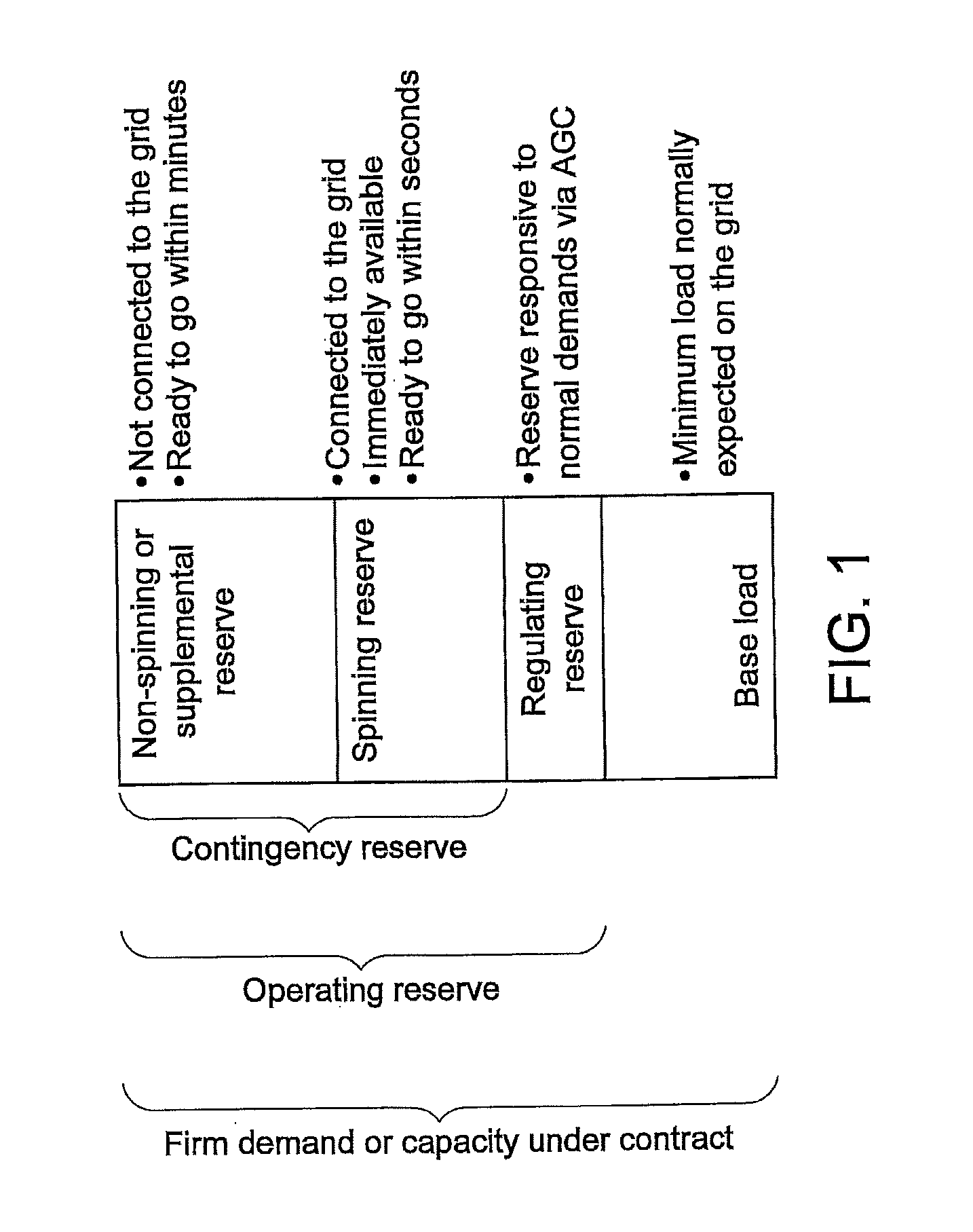
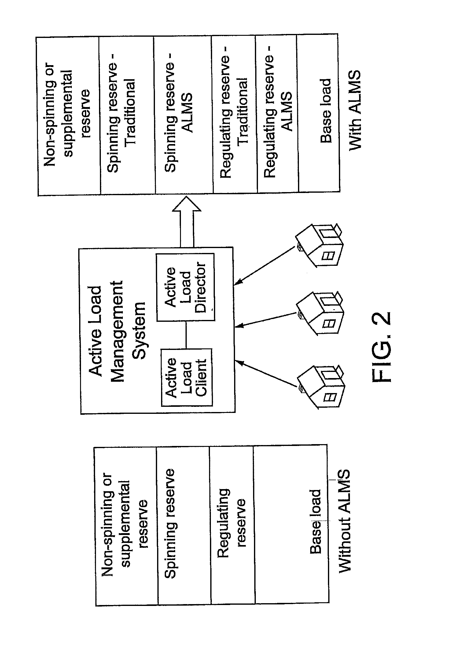
Typically, when additional power is needed for use as economic dispatch, a power utility will make use of its spinning reserve before using its non-spinning reserve because (a) the generation methods used to produce spinning reserve capacity typically tend to be cheaper than the methods, such as one-way traditional demand response, used to produce non-spinning reserve or (b) the consumer impact to produce non-spinning reserve is generally less desirable than the options used to produce spinning reserve due to other considerations, such as environmental concerns.
However, making use of either spinning reserve or non-spinning reserve results in additional costs to the utility because of the costs of fuel, incentives paid to consumers for traditional demand response, maintenance, and so forth.
When demand is greater than supply or capacity (i.e., the utility is under-generating or under-supplying), the quantity (NIA−NIS) is negative, which typically causes ACE to be negative.
If ACE is not maintained close to zero, line frequency can change and cause problems for power consuming devices attached to the electric utility's grid.
However, in actual power system operations, the total mechanical power supplied by the utility's generators is seldom exactly equal to the total electric power consumed by the loads plus the transmission line losses.
Thus, variation in line frequency can occur due to excess supply, as well as due to excess demand.
In addition, current DSM approaches have been limited to use of a single power measuring meter among every one hundred (100) or more service points (e.g., residences and / or businesses).
Accordingly, current DSM approaches are inadequate because they rely on statistical trends and sampling, rather than on empirical data, to make projections and measure actual load removal events.
However, DSM approaches utilizing load-shaping programs do not meet all of the criteria for implementing regulating reserve or spinning reserve, such as being dispatchable within 15 minutes or less.
Current DSM approaches do not facilitate accurate forecasting twenty-four (24) hours in advance due to their heavy reliance on statistics.

Method used


Image

  • System and method for estimating and providing dispatchable operating reserve energy capacity through use of active load management
  • System and method for estimating and providing dispatchable operating reserve energy capacity through use of active load management
  • System and method for estimating and providing dispatchable operating reserve energy capacity through use of active load management

Examples


Embodiment Construction

[0042]Before describing in detail exemplary embodiments that are in accordance with the present invention, it should be observed that the embodiments reside primarily in combinations of apparatus components and processing steps related to actively monitoring and managing power loading at an individual service point (e.g., on an individual subscriber basis) and throughout a utility's service area, as well as determining available or dispatchable operating reserve power derived from projected power savings resulting from monitoring and management of power loading. Accordingly, the apparatus and method components have been represented where appropriate by conventional symbols in the drawings, showing only those specific details that are pertinent to understanding the embodiments of the present invention so as not to obscure the disclosure with details that will be readily apparent to those of ordinary skill in the art having the benefit of the description herein.

[0043]In this document,...


PUM


Abstract

An active load management system (ALMS) is utilized to supply operating reserve to a utility. According to one embodiment, the ALMS determines amounts of power stored in power storage devices located at service points within the utility's service area, and stores the stored power data in a repository. The ALMS also determines an amount of available operating reserve based on at least the stored power data. When the utility needs operating reserve, the ALMS receives a request for operating reserve from the utility. The ALMS then manages a flow of power from the power storage devices to a power grid accessible by the utility responsive to the utility's request, taking into account the amount of available operating reserve. Determination of stored power data may be aided by reports received from control devices located at the service points, where the reports indicate amounts of power stored by the power storage devices.

Description

CROSS REFERENCE TO RELATED APPLICATIONS[0001]This application is a division of co-pending U.S. application Ser. No. 13 / 019,867 filed on Feb. 2, 2011, which application is incorporated herein by this reference as if fully set forth herein. U.S. application Ser. No. 13 / 019,867 is a continuation-in-part of U.S. application Ser. No. 12 / 715,124 filed on Mar. 1, 2010, now U.S. Pat. No. 8,010,812, which is a division of U.S. application Ser. No. 11 / 895,909 filed on Aug. 28, 2007, now U.S. Pat. No. 7,715,951, and is incorporated herein by this reference as if fully set forth herein. U.S. application Ser. No. 13 / 019,867 is also a continuation-in-part of U.S. application Ser. No. 12 / 715,195 filed on Mar. 1, 2010, now U.S. Pat. No. 8,032,233, which is a division of U.S. application Ser. No. 11 / 895,909 filed on Aug. 28, 2007, now U.S. Pat. No. 7,715,951, and is incorporated herein by this reference as if fully set forth herein. U.S. application Ser. No. 13 / 019,867 is further a continuation-in-p...

Claims


Application Information

Patent Timeline
Patent Type & Authority Applications(United States)
IPC IPC(8): G05B15/02G05F1/66
CPCG05B15/02G05F1/66Y04S10/54H02J3/14Y02B70/3225Y04S20/222H02J2003/003Y04S20/224G06Q10/00H02J3/003H02J2310/12H02J3/004Y04S20/00Y02B90/20
Inventor FORBES, JR., JOSEPH, W.
Owner LANDISGYR TECH INC
Learn More