Fluid Flow Measurement Sensor, Method, and Analysis

a technology of fluid flow and measurement sensor, applied in the field of fluid flow measurement sensor, method and analysis, can solve the problems of misleading and non-representative readings, other severe limitations, and difficulty in detecting additional water entering the wellbore , to achieve the effect of reducing the number of wellbore water leakages

Inactive Publication Date: 2014-12-18
REM SCI ENTERPRISES
View PDF22 Cites 11 Cited by
  • Summary
  • Abstract
  • Description
  • Claims
  • Application Information

AI Technical Summary

Benefits of technology

The invention provides a way to measure and process data from arrays of sensors. This can be used to determine the flow rate of a conduit and diagnose any anomalies in the wall of the conduit.

Problems solved by technology

The presence of water already in the wellbore, however, makes detection of the additional water entering the wellbore difficult and often beyond the ability of conventional production logging tools.
Furthermore, in deviated and horizontal wells with multiphase flow, and also in some vertical wells, conventional production logging methods are frequently misleading due to complex and varying flow regimes or patterns that cause misleading and non-representative readings.
Generally, prior art production logging is performed in these complex flow regimes in the central area of the borehole and yields frequently misleading results, or may possess other severe limitations.
Often the location of an influx of water, which is usually the information desired from such logging, is not discernable due to the small change in current measurement responses superimposed upon large variations caused by the multiphase flow conditions.

Method used


Image

  • Fluid Flow Measurement Sensor, Method, and Analysis
  • Fluid Flow Measurement Sensor, Method, and Analysis
  • Fluid Flow Measurement Sensor, Method, and Analysis

Examples


Embodiment Construction

[0027]The making and using of the presently preferred embodiments are discussed in detail below. It should be appreciated, however, that the present invention provides many applicable inventive concepts that can be embodied in a wide variety of specific contexts. The specific embodiments discussed are merely illustrative of specific ways to make and use the invention, and do not limit the scope of the invention.

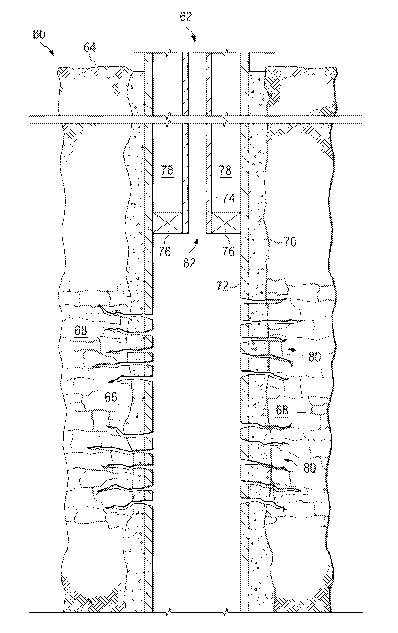
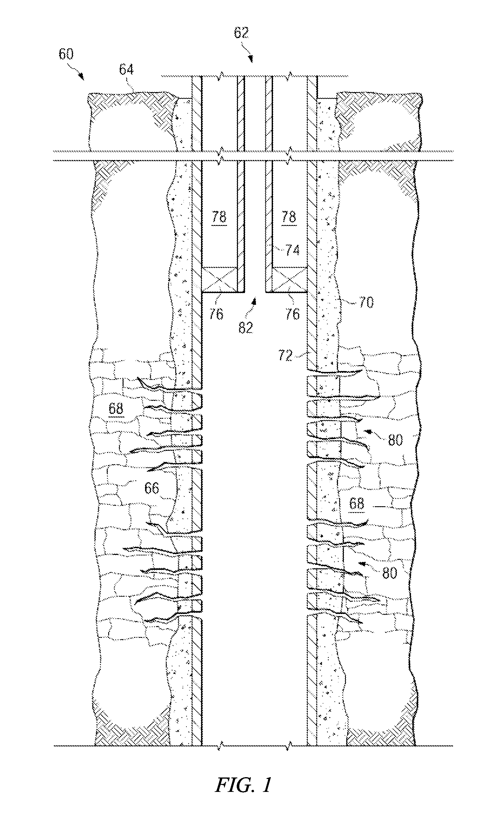
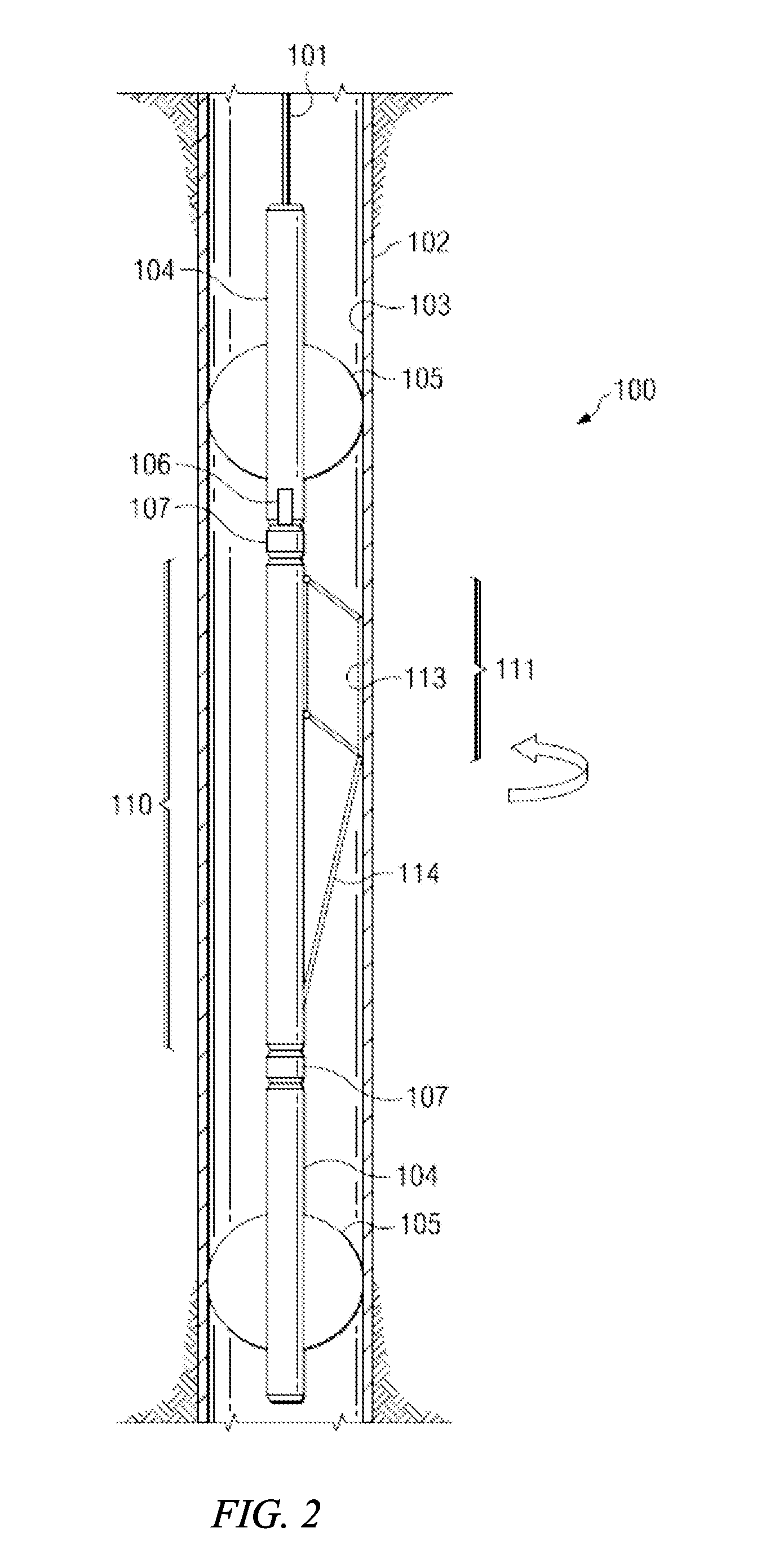
[0028]The present invention will be described with respect to preferred embodiments in a specific context, namely fluid flow measurement in a wellbore and analysis of the measurement data. The invention may also be applied, however, to other applications where the detection of conductive fluid flow is useful, such as pipes, casings, drill shafts, tanks, and swimming pools. The measurement tool may be used in vertical, deviated, and horizontal wells, and may be used in tubing, casing, slotted screens, slotted liners, and almost any well completion. Any type of conduit, wellbor...


PUM


Abstract

Fluid flow measurement sensor, method, and analysis are disclosed, which provide for the measurement and processing of array sensor data. Other embodiments provide for determination of flow rate from the array sensor data, and for diagnosis of a conduit wall anomaly based on anomaly shape.

Description

[0001]This application claims the benefit of U.S. Provisional Application Ser. No. 61 / 491,036, entitled “Fluid Flow Measurement Sensor, Method, and Analysis,” filed on May 27, 2011, which application is hereby incorporated herein by reference.CROSS-REFERENCE TO RELATED APPLICATIONS[0002]This application is related to the following co-pending and commonly-assigned patent applications: application Ser. No. 12 / 987,773, filed Jan. 10, 2011, entitled “Apparatus and Method for Fluid Flow Measurement with Sensor Shielding;” application Ser. No. 12 / 947,402, filed Nov. 16, 2010, entitled “Fluid Flow Measuring Device and Method;” and application Ser. No. 12 / 513,807 (now U.S. Pat. No. 8,156,799), filed May 6, 2009, entitled “Rotating Fluid Flow Measurement Device and Method,” all of which are hereby incorporated herein by reference.TECHNICAL FIELD[0003]The present invention relates generally to measurement of fluid flow, and more particularly to a fluid flow measurement sensor, method, and ana...

Claims


Application Information

Patent Timeline
IPC IPC(8): G01F1/58E21B47/10
CPCG01F1/588G01F1/584E21B47/102G01F1/56G01F1/74E21B47/113E21B47/00E21B47/10G01F1/58
Inventor SIDHWA, FEROZE J.MAUTE, ROBERT E.
Owner REM SCI ENTERPRISES
Why Eureka
Try Eureka