Complex heat dissipation assembly

Inactive Publication Date: 2014-12-18
WU CHE YUAN
View PDF0 Cites 9 Cited by
  • Summary
  • Abstract
  • Description
  • Claims
  • Application Information

AI Technical Summary

Benefits of technology

[0007]It is therefore a primary object of the present invention to provide a complex heat dissipation assembly, which is able to quickly transfer heat generated by a heat source f

Problems solved by technology

In use of the electronic products, the electronic components will inevitably generate a great amount of heat.
In the case that the heat is not efficiently dissipated, the heat will accumulate around the heat source to cause overheating of a local part of the surface of the case.
In use of the electronic products, the electronic components will inevitably generate a great amount of heat.
In the case that the heat is not e

Method used


Image

  • Complex heat dissipation assembly
  • Complex heat dissipation assembly
  • Complex heat dissipation assembly

Examples


first embodiment

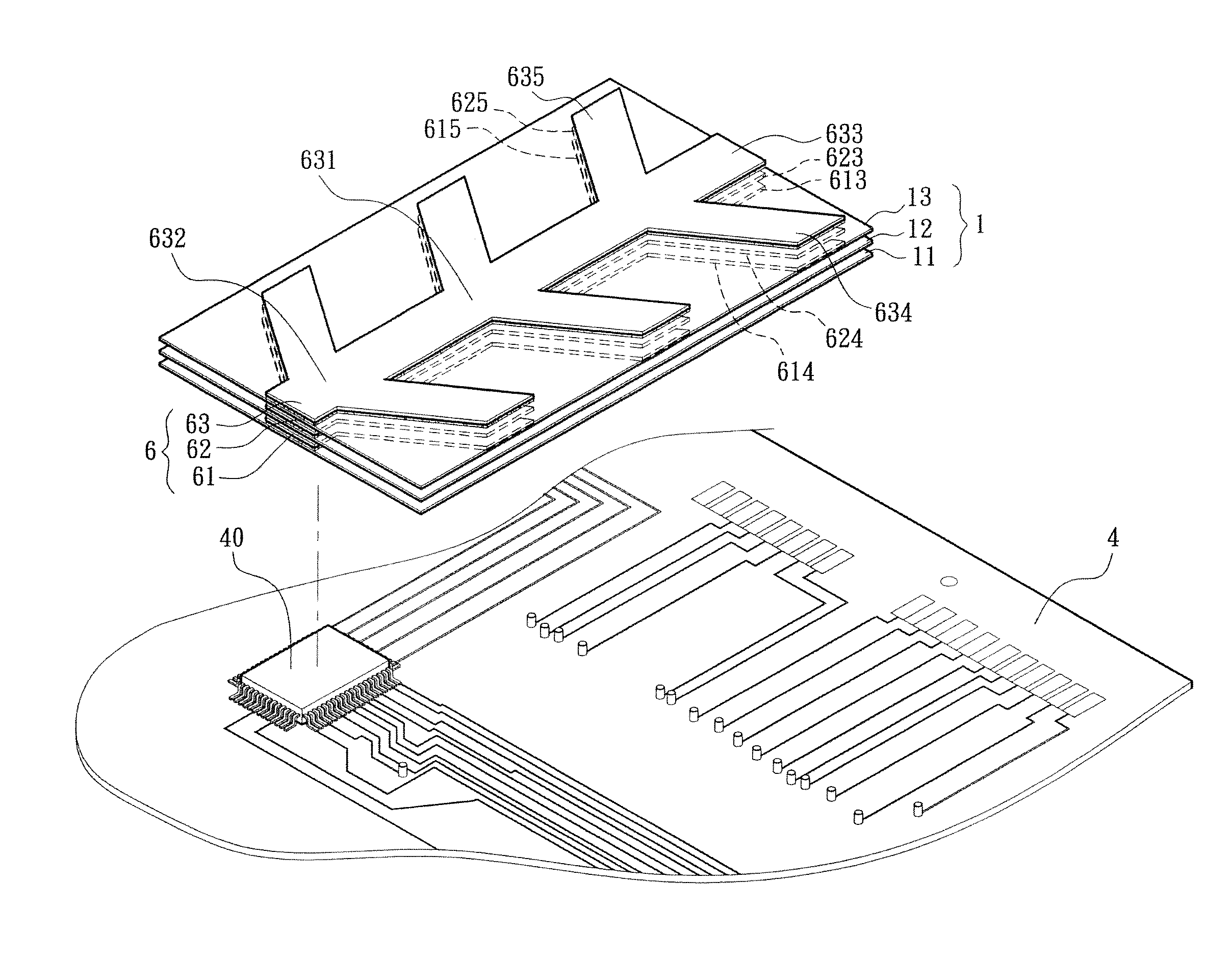
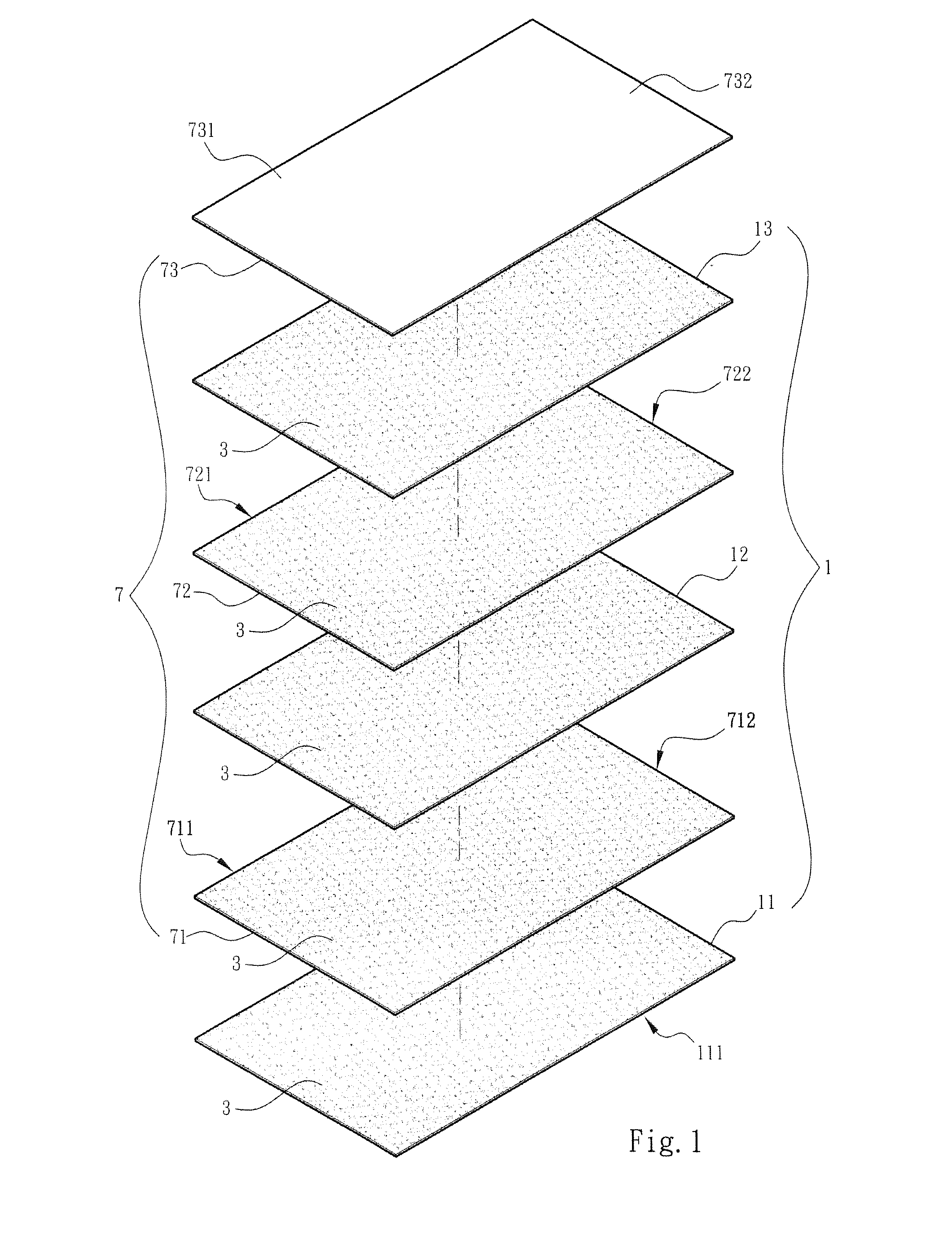
[0033]Please refer to FIG. 1. the complex heat dissipation assembly of the present invention includes a heat conduction plate assembly 1 and a heat spreader assembly 7. The heat conduction plate assembly 1 is composed of multiple sequentially stacked electroconductive heat conduction plates 11, 12, 13, (which can be made of metal material). The outermost surface of the heat conduction plate assembly 1 is defined as a contact face 111. The heat spreader assembly 7 is composed of multiple heat spreaders 71, 72, 73 respectively alternately disposed between the heat conduction plates 11, 12, 13. The heat spreaders 71, 72, 73 are plate-shaped structure bodies with an area equal to that of the heat conduction plates 11, 12, 13. The heat spreaders 71, 72, 73 can be made of graphite or the like material. The heat spreaders 71, 72, 73 have a property of quickly conducting heat along the surface (transversely). In this embodiment, each of the heat spreaders 71, 72, 73 has a proximal-to-heat-...

second embodiment

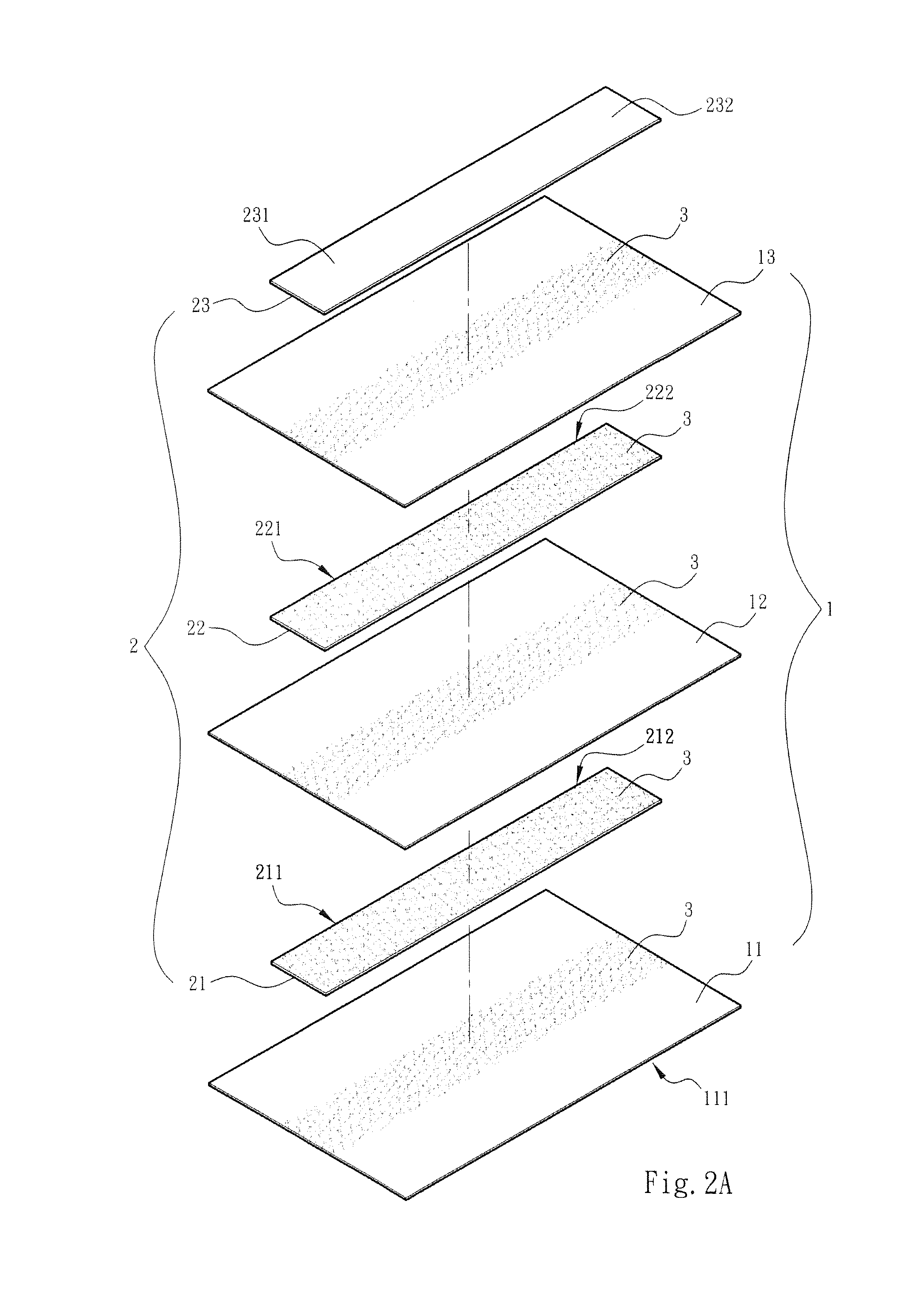
[0034]Please refer to FIGS. 2A, 2B and 3. the complex heat dissipation assembly of the present invention includes a heat conduction plate assembly 1 and a heat spreader assembly 2. The heat conduction plate assembly 1 is composed of multiple sequentially stacked electroconductive heat conduction plates 11, 12, 13, (which can be made of metal material). The outermost surface of the heat conduction plate assembly 1 is defined as a contact face 111. The heat spreader assembly 2 is composed of multiple heat spreaders 21, 22, 23 respectively alternately disposed between the heat conduction plates 11, 12, 13. The heat spreaders 21, 22, 23 are plate-shaped structure bodies with an area small than that of the heat conduction plates 11, 12, 13. The heat spreaders 21, 22, 23 can be made of graphite or the like material. The heat spreaders 21, 22, 23 have a property of quickly conducting heat along the surface (transversely). In this embodiment, the heat spreaders 21, 22, 23 are elongated pla...


PUM


Abstract

A complex heat dissipation assembly, which includes: a heat conduction plate assembly composed of multiple electroconductive heat conduction plates, the heat conduction plate assembly having a contact face in contact with the heat source; and a heat spreader assembly composed of multiple heat spreaders, which are able to quickly transversely conduct heat. The heat spreaders are disposed between the heat conduction plates in contact therewith. Each heat spreader has a proximal-to-heat-source section and a distal-from-heat-source section. The heat conduction plate assembly and the heat spreader assembly cooperate with each other to complexly conduct and spread the heat of the heat source in different directions so as to uniformly and quickly dissipate the heat. Accordingly, the heat is prevented from accumulating around the heat source. In this case, the temperature will not locally abnormally rise.

Description

BACKGROUND OF THE INVENTION[0001]1. Field of the Invention[0002]The present invention relates generally to a complex heat dissipation assembly, and more particularly to a low-cost and simplified heat dissipation structure, which is able to quickly and uniformly dissipate the heat generated by a heat source so as to avoid accumulation of the heat around a local section.[0003]2. Description of the Related Art[0004]In recent years, various electronic products are more and more widely used. The electronic products employ all kinds of operation analytic and power amplification electronic components (such as central processor, light-emitting elements, power transistors and the like components) to provide complicated and sophisticated video / audio effect in operation. In use of the electronic products, the electronic components will inevitably generate a great amount of heat. In the case that the heat is not efficiently dissipated, the heat will accumulate around the heat source to cause ov...

Claims


Application Information

Patent Timeline
IPC IPC(8): H05K7/20
CPCH05K7/2039H01L23/36H01L23/3672H01L2924/0002H01L2924/00
Inventor WU, CHE YUAN
Owner WU CHE YUAN
Why Eureka
Try Eureka