Light source with heat transfer arrangement

Active Publication Date: 2005-02-03
CHEN AMY YUN
View PDF5 Cites 31 Cited by
  • Summary
  • Abstract
  • Description
  • Claims
  • Application Information

AI Technical Summary

Benefits of technology

[0010] Another object of the present invention is to provide a light source with a heat transfer arrangement, wherein the cooling agent has a high heat conductivity to quickly and effectively transfer the heat away from the light source to the heat sink.
[0011] Another object of the present invention is to provide a light source with a heat transfer arrangement, wherein the heat transfer of the light source is a process of evaporation and condensation of the cooling a gent. In other words, the heat from the light source vaporizes the coo

Problems solved by technology

However, when a plurality of light sources consumes electricity at the same time, the heat generated from the light sources may cause a short circuit.
In other words, the problem of overheat is one of the common drawbacks of the conventional light sources.
However, the heat sink and the light source is in an integral s

Method used


Image

  • Light source with heat transfer arrangement
  • Light source with heat transfer arrangement
  • Light source with heat transfer arrangement

Examples


Embodiment Construction

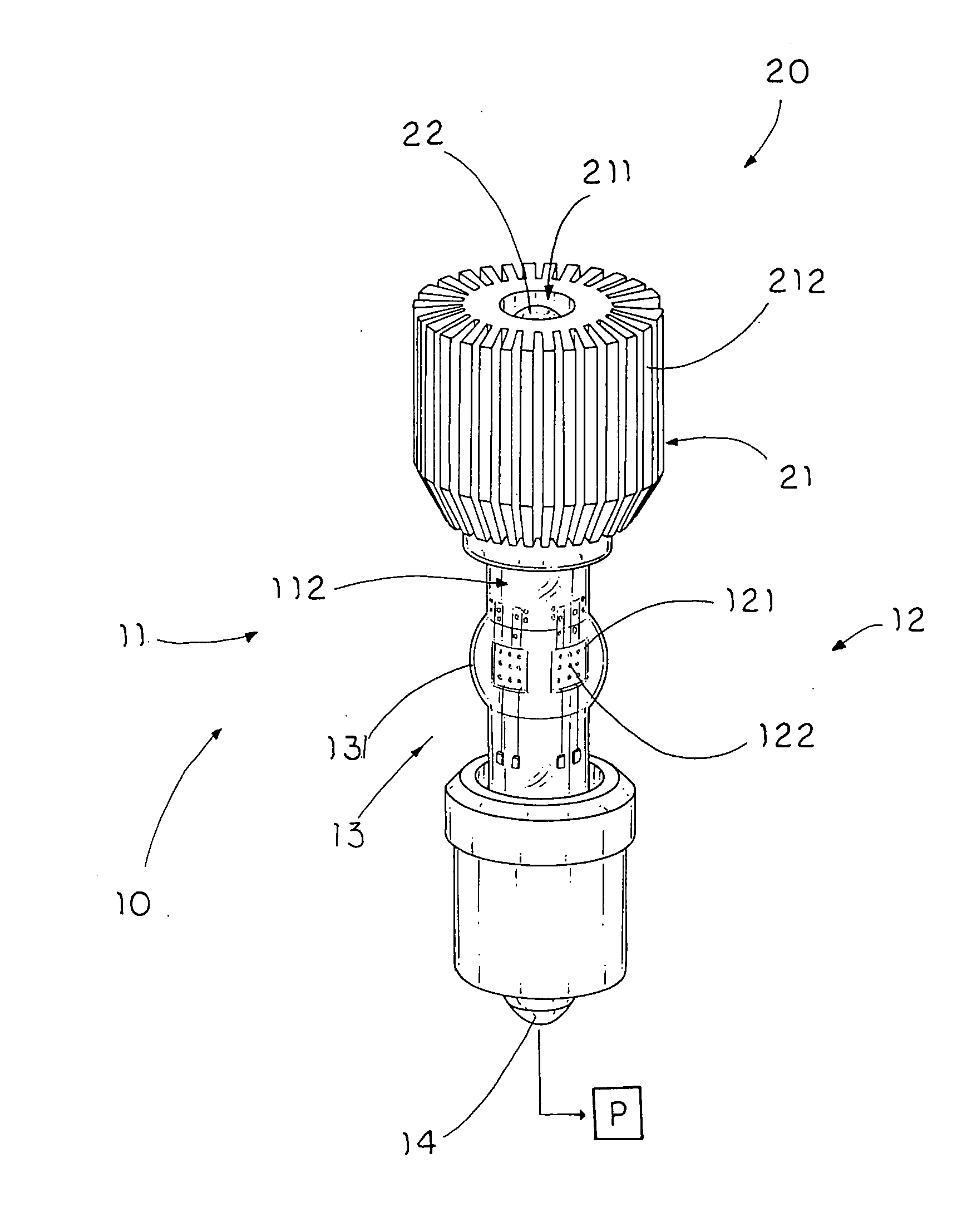
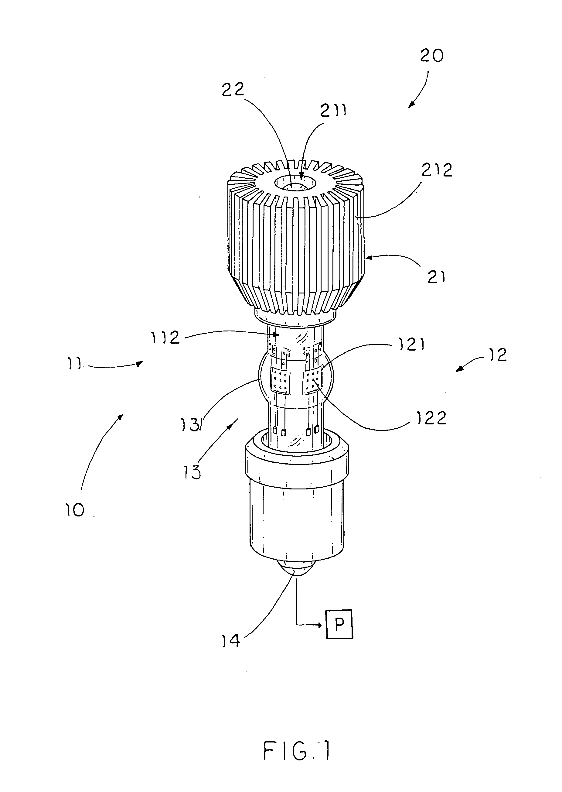
[0028] Referring to FIG. 1 of the drawings, a light source according to a first preferred embodiment of the present invention is illustrated, wherein the light source comprises a light head 10 and a heat transfer arrangement 20 for dissipating heat generated from the light head 10.

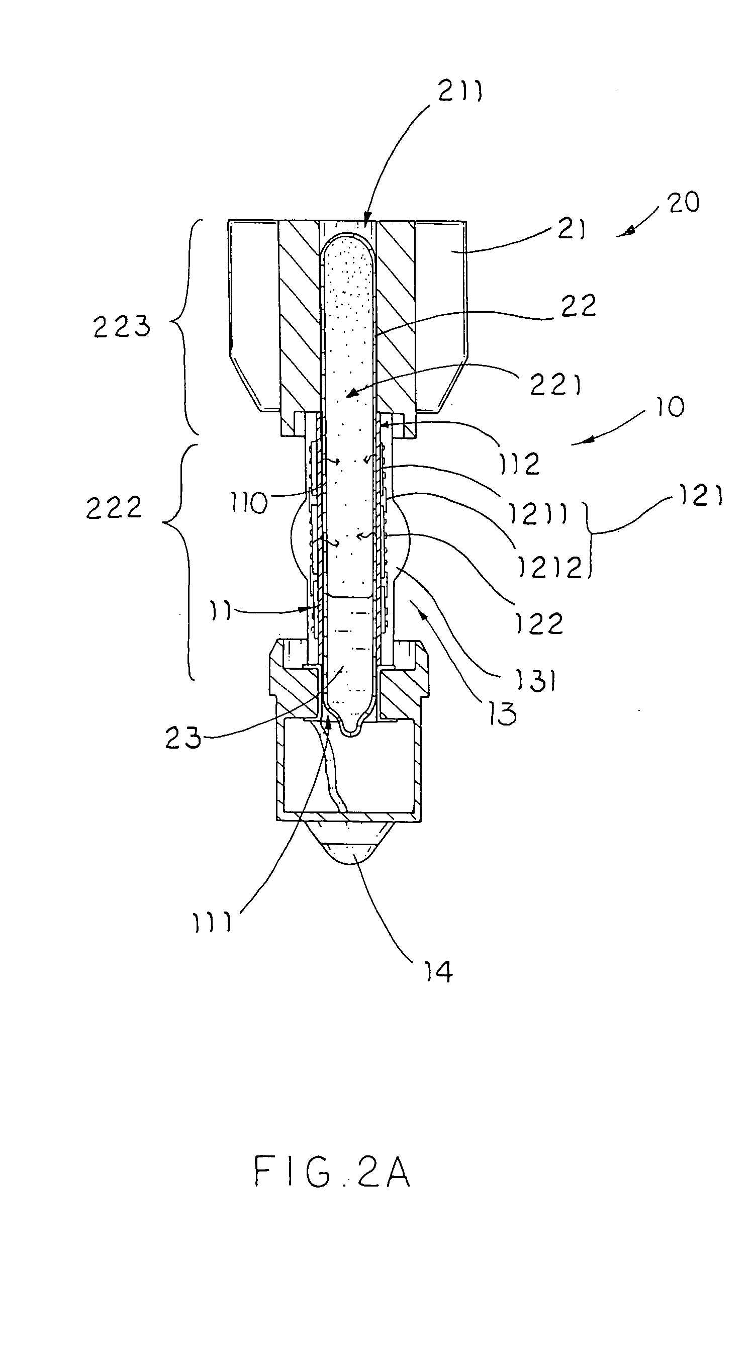
[0029] The light head 10 comprises a tubular supporting frame 11 having an interior space 111 and a peripheral surface 112, and a luminary unit 12 comprising a circuit 121 provided on the peripheral surface 112 of the supporting frame 11 for electrically connecting a power source P, and at least a luminary element 122 electrically connected to the circuit 121 for emitting light.

[0030] The heat transfer arrangement 20 comprises a heat sink 21, a heat conductor 22 having a sealed chamber 221, and a cooling agent 23 contained in the sealed chamber 221. The sealed chamber has a first portion 222 positioned in the interior space 111 of the supporting frame 11 and a second portion 223 extended to the heat sink...


PUM


Abstract

A light source includes a light head and a heat transfer arrangement. The light head includes a tubular supporting frame, which has an interior space, and a luminary unit provided on the supporting frame. The heat transfer arrangement, for dissipating heat generated from the light head, includes a heat sink and a heat conductor having a sealed chamber, which has a first portion in the supporting frame and a second portion extended to the heat sink, and a cooling agent contained in the sealed chamber of the heat conductor, wherein the cooling agent is capable of being vaporized by the heat of the luminary unit and condensed by said heat sink so as to substantially enable the heat to flow from the luminary unit towards the heat sink.

Description

BACKGROUND OF THE PRESENT INVENTION [0001] 1. Field of Invention [0002] The present invention relates to a light source arrangement, and more particularly to a light source with a heat transfer arrangement which comprises a cooling agent contained in an air-sealed chamber for substantially dissipating the heat from the light source through the phase equilibrium process of the cooling agent. [0003] 2. Description of Related Arts [0004] Nowadays, the most common light sources for illumination are filament lamp bulb and LED lighting. Due to the remarkable features of low power consumption and instant light emission, LED lighting is specially adapted to be utilized in many electrical appliances, such as the power on-off signal light and instructional signal light of electric equipment, indicating light of electronic clock, and etc. . . . [0005] Due to the technology of LED, the LED, nowadays, not only has excellent properties of low power consumption and instant light emission but also ...

Claims


Application Information

Patent Timeline
IPC IPC(8): F21K2/00F21K99/00F21V29/00
CPCF21K9/00F21V29/004F21V29/006F21Y2101/02Y10S362/80F28D15/046F21V29/85F21V3/02F21K9/135F21V5/04F28D15/0275F21V29/773F21V29/74F21V29/89F21K9/232F21Y2115/10
Inventor ZHANG, LONG BAO
Owner CHEN AMY YUN
Why Eureka
Try Eureka