
Method of friction stir welding

a friction stir welding and stir welding technology, applied in welding/soldering/cutting articles, non-electric welding apparatus, manufacturing tools, etc., can solve the problems of significant reduction of the strength of the weld joint material, further compromise of the strength of the fusion weld joint between dissimilar materials, especially metal alloys, and no longer aligned and/or parallel rotating tools and joint interfaces. , to achieve the effect of improving metallurgical bonding, less wear and less wear

Inactive Publication Date: 2014-12-18
FOCUS HOPE
View PDF10 Cites 26 Cited by
  • Summary
  • Abstract
  • Description
  • Claims
  • Application Information

AI Technical Summary

Benefits of technology

The method described in this patent results in better contact between the stir tool and the joint interface, which leads to a stronger weld joint with improved metallurgical bonding. Additionally, this method reduces wear and tear on the stir tool.

Problems solved by technology

This process can significantly reduce the strength of the weld joint material.
Furthermore, the strength of a fusion weld joint between dissimilar materials, particularly metal alloys, is further compromised because of inherent chemical reactions which occur between differing material compounds when heated above or near melting temperatures.
However, when the rotating tool is tilted in such a manner with only a back tilt (and lacking a side tilt), the rotating tool and the joint interface are no longer aligned and / or parallel.
This misalignment results in less than optimum contact between the rotating tool and the joint materials and may result in greater tool wear.
However dissimilar alloys from different base metals (e.g. aluminum and steel) have vastly different solidus temperatures.
It may be undesirable to allow the metal alloy with the lower solidus temperature to liquefy.

Method used


Image

  • Method of friction stir welding
  • Method of friction stir welding
  • Method of friction stir welding

Examples


Embodiment Construction

[0039]Various embodiments are described herein to various apparatuses, systems, and / or methods. Numerous specific details are set forth to provide a thorough understanding of the overall structure, function, manufacture, and use of the embodiments as described in the specification and illustrated in the accompanying drawings. It will be understood by those skilled in the art, however, that the embodiments may be practiced without such specific details. In other instances, well-known operations, components, and elements have not been described in detail so as not to obscure the embodiments described in the specification. Those of ordinary skill in the art will understand that the embodiments described and illustrated herein are non-limiting examples, and thus it can be appreciated that the specific structural and functional details disclosed herein may be representative and do not necessarily limit the scope of the embodiments.

[0040]Reference throughout the specification to “various ...


PUM

PropertyMeasurementUnit
angleaaaaaaaaaa
angleaaaaaaaaaa
anglesaaaaaaaaaa

Abstract

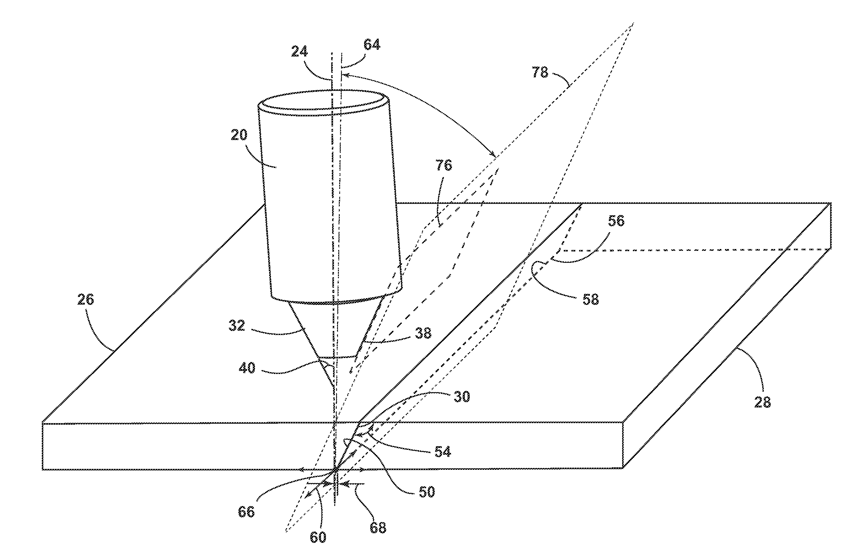
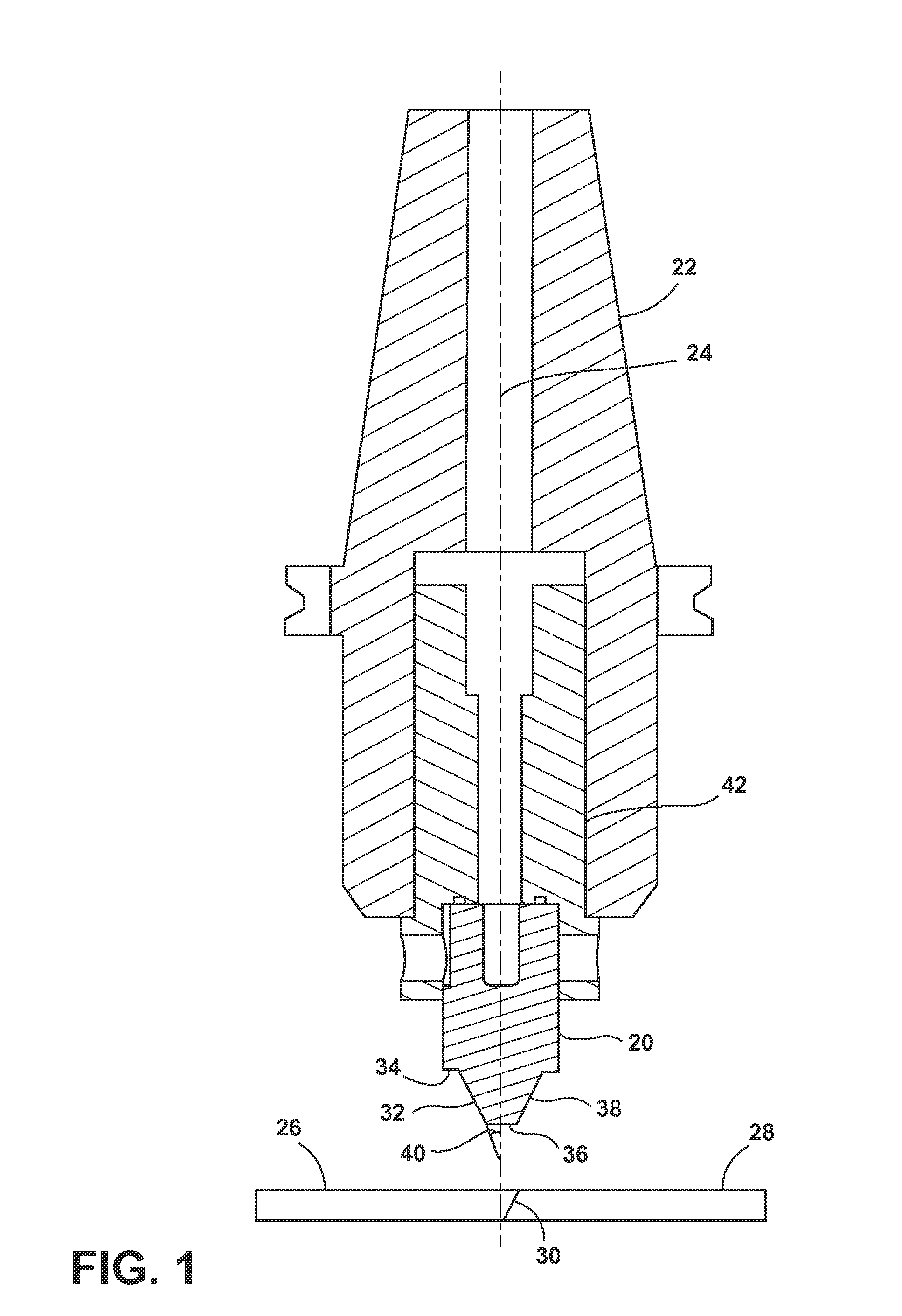
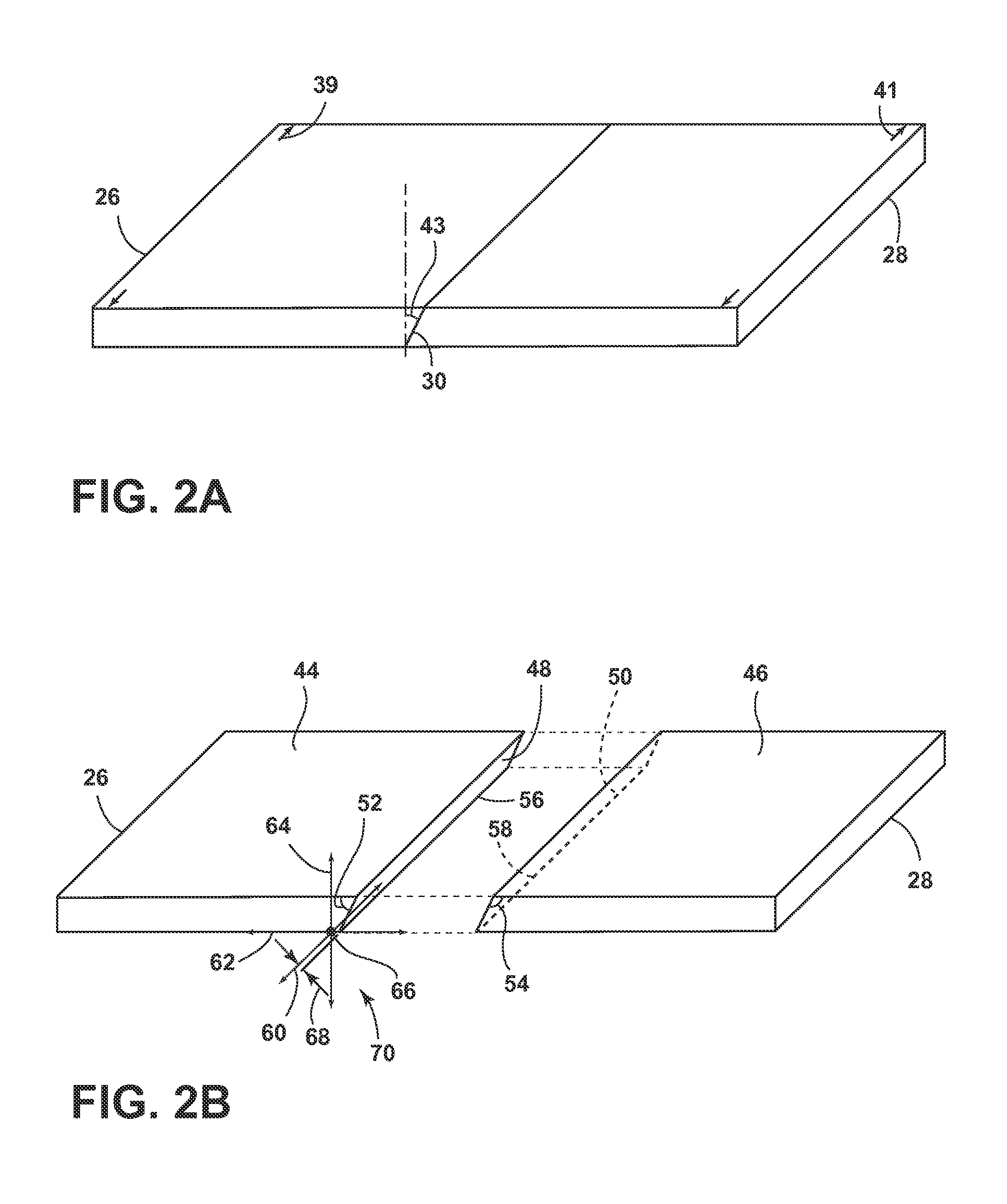
A method of friction stir welding is provided. The method includes providing a stir tool configured to rotate about and move along a stir tool axis and includes a pin with a pin axial end surface and a pin tapered surface that extends radially outwardly from the pin axial end surface. The method further includes providing the first member with a first member faying surface and defining a normal line that is normal to the first member top surface, is perpendicular to a longitudinal axis, and extends through a reference point. The method further includes providing the second member with a second member faying surface and forming a joint interface between the first and second members. The method further comprises contacting the rotating pin with the second member faying surface, the stir tool axis being disposed at a side tilt angle upon contact.

Description

CROSS-REFERENCE TO RELATED APPLICATION[0001]This application claims the benefit of U.S. provisional application No. 61 / 836,320, filed Jun. 18, 2013, which is hereby incorporated by reference as though fully set forth herein.STATEMENT REGARDING FEDERALLY SPONSORED RESEARCH & DEVELOPMENT[0002]This invention was made with government support under Contract No. W56 HZV-05-C-0721 awarded by the U.S. Army Tank Automotive Research, Development, and Engineering Center. The government has certain rights in the invention.BACKGROUND[0003]a. Technical Field[0004]The field of the present disclosure generally relates to a method of friction stir welding. In particular, this disclosure relates to a method of friction stir welding whereby various angles of the components involved correspond to one another and whereby heat is selectively removed from one of the workpieces to form a stronger weld joint.[0005]b. Background Art[0006]This background description is set forth below for the purpose of provi...

Claims


Application Information

Patent Timeline
Patent Type & Authority Applications(United States)
IPC IPC(8): B23K20/12
CPCB23K20/1225B23K20/122B23K2103/14B23K2103/18B23K2103/20B23K2103/26
Inventor DINDA, GURU P.GRAY, MICHAEL D.MILLER, RICHARD E.
Owner FOCUS HOPE
Learn More