Method for Monitoring a Battery

Active Publication Date: 2014-12-18
ROBERT BOSCH GMBH
View PDF10 Cites 4 Cited by
  • Summary
  • Abstract
  • Description
  • Claims
  • Application Information

AI Technical Summary

Benefits of technology

[0011]Thus, the method set forth is used for recording variables, such as measured variables or parameters or physical variables, e.g., in accumulator modules, for, in particular, measuring cell temperature in accumulator modules of hybrid or electric vehicles. Consequently, the measurement

Problems solved by technology

However, further parameters, such as the temperature, are only measured in a small portion of

Method used


Image

  • Method for Monitoring a Battery
  • Method for Monitoring a Battery

Examples


Example

[0037]The present invention is represented schematically in the drawing in light of specific embodiments, and is described in detail below with reference to the drawing.

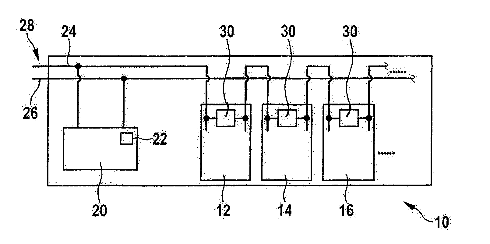
[0038]A schematic representation of a variant of a battery, which is denoted, on the whole, by the reference numeral 10, is illustrated in FIG. 1. A number of cells, of which only a first cell 12, a second cell 14 and a third cell 16 are shown for the sake of clarity, are situated in this battery. In addition, a control unit 20 is provided in the battery; a central receiver 22 being positioned, in turn, in the control unit.

[0039]In order to make available the electrical energy converted by cells 12, 14 and 16, current bars 24 and 26 are provided as supply lines, which supply the electrical energy at a terminal 28 of battery 10. To this end, current bars 24 and 26 are each connected to cells 12, 14 and 16. In addition, control unit 20 is connected to cells 12, 14 and 16 via current bars 24 and 26, so that control unit...


PUM


Abstract

In a method for monitoring a battery which includes a number of cells, in each instance, at least one electronic unit is situated so as to be in contact with at least two of the cells, in order to record a variable of this cell and forward it to a central receiver.

Description

BACKGROUND OF THE INVENTION[0001]1. Field of the Invention[0002]The present invention relates to a method for monitoring a battery and a battery that is configured to carry out the method.[0003]2. Description of the Related Art[0004]An interconnection of several galvanic cells, which are, as a rule, substantially identical, is referred to as a battery. It constitutes an electrochemical energy store and an energy converter and is provided for supplying electrical energy. When discharging occurs in the battery, stored chemical energy is converted to electrical energy by the electrochemical reaction. The cells of the battery, which may be connected in parallel or in series or a mixture of the two, are arranged in so-called modules. One or more of these modules, connected in series or parallel, form the battery.[0005]In the case of the above-mentioned cells, primary cells, which are not rechargeable, are distinguished from secondary cells, which are rechargeable. A rechargeable battery ...

Claims


Application Information

Patent Timeline
IPC IPC(8): H01M10/48G01R31/36H01M50/51H01M50/512
CPCH01M10/486G01R31/362H01M10/482G01R31/3835H01M10/4207H01M10/4235H01M10/425H01M10/4257H01M2220/20H01M2010/4278H01M2010/4271H01M2200/10G01R31/396G01K2205/00H01M50/51H01M50/512G01K13/00G01K15/00Y02E60/10Y02P70/50H01M10/0431
Inventor HENRICI, FABIAN
Owner ROBERT BOSCH GMBH
Why Eureka
Try Eureka